
Specifications


© 2008-2012 Microchip Technology Inc. DS70323E-page 43-77
Section 43. High-Speed PWM
High-Speed PWM
43
43.10.7.1 CONFIGURATION OF CURRENT RESET MODE
A current-limit signal resets the time base for the affected PWM generator with the following
configuration:
- The CLMOD bit for the PWM generator is ‘0’.
- The External PWM Reset Control bit, XPRES (PWMCONx<1>) is ‘1’.
- The PWM generator is in Independent Time Base mode (ITB = 1).
The configuration of Current Reset mode is shown in Example 43-21. For more information, refer
to 43.16.5 “Current Reset PWM”.
Example 43-21: Configuration of Current Reset Mode
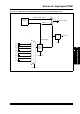
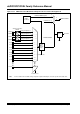
The PWM current-limit circuit logic diagram is illustrated in Figure 43-36. The selection of input
and output sources for remappable pins is shown in Table 43-6 and Table 43-7.
Figure 43-36: PWM Current-Limit Control Circuit Logic Diagram for Devices with Remappable I/O
/* Configuration of Current Reset mode */
FCLCONxbits.CLMOD = 0; /* Current-limit mode is disabled */
PWMCONxbits.XPRES = 1; /* External PWM Reset mode is enabled */
PWMCONxbits.ITB = 1; /* Independent Time Base mode is enabled */
CLSRC<4:0>
FLT1
FLT2
FLT3
FLT4
FLT5
FLT6
FLT7
FLT8
00000
00001
00010
00011
00100
00111
00101
00110
0
1
PWMxH, PWMxL
2
PWM
Generator #
CLDAT<1:0>
2
PWMxH, PWMxL Signals
2
Cycle-by-Cycle
Mode
PMTMR
CLMOD<1:0>
EN
XPRES