
Specifications


dsPIC33F/PIC24H Family Reference Manual
DS70323E-page 43-72 © 2008-2012 Microchip Technology Inc.
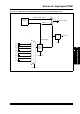
Figure 43-34: PWM Fault Control Module Block Diagram for Devices without Remappable I/O
FLTSRC<4:0>
CMP1x
CMP2x
CMP3x
CMP4x
FLT1
FLT2
FLT3
FLT4
FLT5
FLT6
FLT7
FLT8
00000
00001
00010
01000
01001
01010
01011
01100
01111
00011
01101
01110
Analog Comparator 1
Analog Comparator 2
Analog Comparator 3
Analog Comparator 4
Analog Comparator
Module
0
1
PWMxH, PWMxL
2
PWM
Generator #
FLTDAT<1:0>
2
PWMxH, PWMxL Signals
2
Fault
Mode
Selection
Logic
FLTMOD<1:0>
Latch
Clear
FLTSTAT
PMTMR/SMTMR
FLT23
11110
Note: For more details on the available analog comparator outputs and Fault pins, refer to the specific device data sheet.