
Specifications


dsPIC33F/PIC24H Family Reference Manual
DS70323E-page 43-66 © 2008-2012 Microchip Technology Inc.
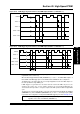
43.9.3 Redundant PWM Output Mode
In Redundant PWM Output mode, the High-Speed PWM module has the ability to provide two
copies of a single-ended PWM output signal per PWM pin pair (PWMxH, PWMxL). This mode
uses the PDCx register to specify the duty cycle. In this output mode, the two PWM output pins
provide the same PWM signal unless the user-assigned application specifies an override value.
Redundant PWM Output mode is illustrated in Figure 43-31.
Figure 43-31: Redundant PWM Output Mode
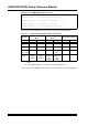
Table 43-3 provides the PWM register functionality for the PWM modes.
Table 43-3: Complementary, Push-Pull and Redundant PWM Output Mode Register
Functionality
Time
Base
Primary Master
Time Base
Secondary Master
Time Base
(1)
Independent Time Base
Function PWMxH PWMxL PWMxH PWMxL PWMxH PWMxL
PWM
Period
PTPER PTPER STPER STPER PHASEx PHASEx
PWM
Duty
Cycle
MDC/PDC
X MDC/PDCX MCD/PDCx MDC/PDCx MDC/PDCx MDC/PDCx
PWM
Phase
Shift
PHASEx PHASEx PHASEx PHASEx N/A N/A
ADC
Trigger
SEVTCMP/
TRIGx/
STRIGx
SEVTCMP/
TRIGx/
STRIGx
SSEV-
TCMP/TRI
Gx/
STRIGx
SSEV-
TCMP/TRI
Gx/
STRIGx
SEVTCMP
(2)
/SSEV-
TCMP
(2)
/TRI
Gx/
STRIGx
SEVTCMP
(2)
/SSEV-
TCMP
(2)
/TRI
Gx/
STRIGx
Note 1: Refer to the specific device data sheet for the availability of Secondary Master
Time Base.
2: Selection of trigger source as SEVTCMP or SSEVTCMP depends on the MTBS
(PWMCONx<3>) bit setting. Refer to the specific device data sheet for the availability
of MTBS bit.
Duty Cycle
0
Period
Timer
Value
PWMxH
Value
Programmed
Duty
Cycle
PWMxL