
Specifications


© 2008-2012 Microchip Technology Inc. DS70323E-page 43-65
Section 43. High-Speed PWM
High-Speed PWM
43
43.9 PWM OPERATING MODES
This section describes the following operation modes, which are supported by the High-Speed
PWM module:
• Push-Pull PWM Output Mode
• Complementary PWM Output Mode
• Redundant PWM Output Mode
• True Independent PWM Output Mode
These operating modes can be selected using the PWM # I/O Pin Mode bits (PMOD<1:0>) in the
PWM I/O Control register (IOCONx<11:10>).
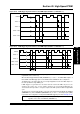
43.9.1 Push-Pull PWM Output Mode
In Push-Pull PWM Output mode, the PWM outputs are alternately available on the PWMxH and
PWMxL pins. Some typical applications of Push-Pull mode are provided in 43.16 “Application
Information”. The PWM outputs in the Push-Pull PWM mode are illustrated in Figure 43-29.
Figure 43-29: Push-Pull PWM Output Mode
43.9.2 Complementary PWM Output Mode
In Complementary PWM Output mode, the PWM output PWMxH, is the complement of the
PWMxL output. Some typical applications of Complementary PWM Output mode are provided
in 43.16 “Application Information”.
The PWM outputs when the module operates in Complementary PWM Output mode are
illustrated in Figure 43-30.
Figure 43-30: Complementary PWM Output Mode
PWM1H
PWM1L
DC
X - DTR
Period - DC
X + DTR
T
ON
TOFF
Period Period
Dead Time Dead Time Dead Time
Period
Duty Cycle
0
Period
Timer
Value
Timer Resets
PWMxH
Value
PWMxL
Duty Cycle
Duty Cycle Match
PWM1L
PWM1H
Dead Time
(1)
Dead Time
(1)
Dead Time
(1)
Period
Period
Duty Cycle
0
Period
Timer
Value
Timer Resets
PWMxH
Value
PWMxL (Period-duty cycle)
Duty Cycle Match
Note 1: Positive Dead Time is shown.