
Specifications


© 2008-2012 Microchip Technology Inc. DS70323E-page 43-61
Section 43. High-Speed PWM
High-Speed PWM
43
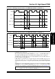
Figure 43-26: PWM Trigger Signal in Relation to the PWM Output (TRGDIV = 2, TRGSTRT = 2)
Figure 43-27: PWM Trigger Signal in Relation to the PWM Output (TRGDIV = 2, TRGSTRT = 3)
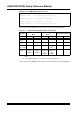
The trigger divider allows the user-assigned application to tailor the ADC sample rates to the
requirements of the control loop.
When the Dual Trigger Mode bit, DTM (TRGCONx<7>), is set to ‘1’, the ADC TRIGx output is a
Boolean OR of the ADC trigger pulses for the TRIGx and the STRIGx time base comparisons.
The DTM mode of operation allows the user-assigned application to take two ADC samples on
the same pin within a single PWM cycle.
If ADC triggers are generated at a rate faster than the rate that the ADC can process, the
operation can result in loss of some samples. However, the user-assigned application can
ensure that the time it provides is enough to complete two ADC operations within a single PWM
cycle.
The trigger pulse is generated regardless of the state of the Trigger Interrupt Enable bit, TRGIEN
(PWMCONx<10>). If the TRGIEN bit (PWMCONx<10>) is set to ‘1’, an interrupt request (IRQ)
is generated. The configuration of independent PWM ADC triggering is shown in Example 43-18.
PWMxH
TRIGx = 0
TRIGx = 8
TRIGx = 4808
TRIGx = 9616
1
PTPER = 9616
534
67
PWMxH
TRIGx = 0
TRIGx = 8
TRIGx = 4808
TRIGx = 9616
1
PTPER = 9616
645
7
8
9
10
11
Note: The secondary trigger comparison (STRIGx) does not generate PWM interrupts
regardless of the state of the DTM bit (TRGCONx<7>).