
Specifications


© 2008-2012 Microchip Technology Inc. DS70323E-page 43-57
Section 43. High-Speed PWM
High-Speed PWM
43
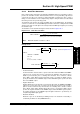
43.7 PWM TRIGGERS
For the ADC module, the TRIGx and STRIGx registers specify the triggering point for the
PWMxH and PWMxL outputs, respectively. An ADC trigger signal is generated when the
independent time base counter (PTMRx or STMRx) register value matches with the specified
TRIGx or STRIGx register value.
The Output Divider bits (TRGDIV<3:0>) in the PWM Trigger Control register (TRGCONx<15:12)
act as a postscaler for the TRIGx register to generate ADC triggers. This allows the trigger signal
to the ADC to be generated once for every 1, 2, 3.... and 16 trigger events. These bits specify
how frequently the ADC trigger is generated.
Each PWM generator consists of the Trigger Postscaler Start Enable Select bits,
TRGSTRT<5:0> (TRGCONx <5:0>), that specify how many PWM cycles to wait before
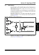
generating the first ADC trigger. The logic for ADC triggering by the High-Speed PWM module is
illustrated in Figure 43-19.
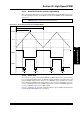
Figure 43-19: PWM Trigger for Analog-to-Digital Conversion
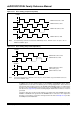
Depending on the settings of the TRGDIV<3:0> bits (TRGCONx<15:12>) and the
TRGSTRT<5:0> bits (TRGCONx <5:0>), triggers are generated at different PWM intervals, as
illustrated in Figure 43-20 through Figure 43-27.
PTMRx
TRIGx
STMRx
STRIGx
1:1
1:16
1:1
.
.
1:16
1
0
PWMx Trigger to ADC
TRGSTRT
DTM
Clock
Clock
PWMxL Trigger to ADC
.
.
.
.
Delay
TRGDIV
PWM Trigger Interrupt, PWMxH Trigger to ADC
CMP
CMP
0