
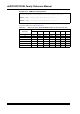
Specifications


© 2008-2012 Microchip Technology Inc. DS70323E-page 43-51
Section 43. High-Speed PWM
High-Speed PWM
43
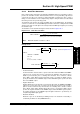
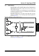
43.6.4 Dead Time Generators
Each complementary output pair for the High-Speed PWM module has a 12-bit down counter to
produce the dead time insertion. Each dead time unit has a rising and falling edge detector
connected to the duty cycle comparison output. Depending on whether the edge is rising or
falling, one of the transitions on the complementary outputs is delayed until the associated dead
time timer generates the specific delay period.
The dead time logic monitors the rising and falling edges of the PWM signals. The dead time
counters reset when the associated PWM signal is inactive and starts counting when the PWM
signal is active. Any selected signal source that provides the PWM output signal is processed by
the dead time logic.
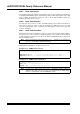
The dead time can be determined using the formula shown in Equation 43-7:
Equation 43-7: Dead Time Calculation
Example 43-14:
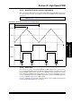
There are three Dead Time Control modes:
• Positive Dead Time
Positive Dead Time mode describes a period of time when both the PWMxH and PWMxL
outputs are not asserted. This mode is useful when the application must allocate time to
disable a power transistor prior to enabling other transistors. This is similar to a “Break
before Make” switch. When Positive Dead Time mode is specified, the DTRx registers
specify the dead time for the PWMxH output, and the ALTDTRx register specifies the dead
time for the PWMxL output.
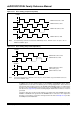
• Negative Dead Time
Negative Dead Time mode describes a period of time when both the PWMxH and PWMxL
outputs are asserted. This mode is useful in current fed topologies that need to provide a
path for current to flow when the power transistors are switching. This is similar to a “Make
before Break” switch. When Negative Dead Time mode is specified, the DTRx register
specifies the negative dead time for the PWMxL output, and the ALTDTRx register specifies
the negative dead time for the PWMxH output. Negative dead time is specified only for
complementary PWM output signals.
• Dead Time Disabled
Dead time logic can be disabled per PWM generator. The dead time functionality is
controlled by the DTC<1:0> bits (PWMCONx<7:6>).
PWM Input Clock Prescaler Divider (PCLKDIV)
ACLK
*
8
*
DTRX, ALTDTRX =
Desired Dead Time
Note: Maximum dead time resolution is 1.04 ns.
7.49 MHz
1
*
16
ACLK
=
=
119.84 MHz
Where,
M1
=
16
REFCLK
= 7.49 MHz
N
=
1
DTRx
,
ALTDTRx
=
Desired Dead Time = 100 ns
119.84 MHz
1
*
8
=
96
100 ns
*
(Refer to Equation 43-1)