
Specifications


dsPIC33F/PIC24H Family Reference Manual
DS70323E-page 43-50 © 2008-2012 Microchip Technology Inc.
43.6.3 Dead Time Generation
Dead time refers to a programmable period of time (specified by the Dead Time register (DTRx)
or the Alternate Dead Time registers (ALTDTRx)), which prevents a PWM output from being
asserted until its complementary PWM signal has been deasserted for the specified time.
The High-Speed PWM module consists of four dead time control units. Each dead time control
unit has its own dead time value.
Dead time generation can be provided when any of the PWM I/O pin pairs are operating in
Complementary PWM Output mode. Many power converter circuits require dead time because
power transistors cannot switch instantaneously. To prevent current shoot-through, some amount
of time must be provided between the turn-off event of one PWM output and the turn-on event of
the other PWM output in a complementary pair or the turn-on event of the other transistor.
The High-Speed PWM module provides the positive dead time and negative dead time. The
positive dead time prevents overlapping of PWM outputs. Positive dead time generation is
available for all output modes. Positive dead time circuitry works by blanking the leading edge of
the PWM signal. Negative dead time is the forced overlap of the PWMxH and PWMxL signals.
Negative dead time works when the extended time period of the currently active PWM output
overlaps the PWM output that is just asserted. Certain converter techniques require a limited
amount of current shoot-through.
Negative dead time is specified only for complementary PWM signals. Negative dead time does
not apply to user or current-limit, or fault overrides. This mode can be implemented by using
phase shift values in the PHASEx/SPHASEx registers that shift the PWM outputs so that the
outputs overlap another PWM signal from a different PWM output channel.
The dead time logic acts as a gate and allows an asserted PWM signal or an override value to
propagate to the output. The dead time logic never asserts a PWM output on its own initiative.
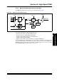
The dual dead time waveforms for dead time disabled, positive dead time and negative dead time
are illustrated in Figure 43-14.
Figure 43-14: Dual Dead Time Waveforms
The Dead Time feature can be disabled for each PWM generator. The dead time functionality is
controlled by the Dead Time Control bits, DTC<1:0> (PWMCONx<7:6>). Dead time is not
supported for Independent PWM Output mode.
PWMxH
PWMxL
PWMxL
PWMxL
PWMxH
PWMxH
Dead Time Disabled
Positive Dead Time
DTRx
ALTDTRx
Negative Dead Time