
Specifications


© 2008-2012 Microchip Technology Inc. DS70323E-page 43-45
Section 43. High-Speed PWM
High-Speed PWM
43
43.6 PWM GENERATOR
This section describes the functionality of the PWM generator.
43.6.1 PWM Period
The PWM period value defines the switching frequency of the PWM pulses. The PWM period
value can be controlled either by the PTPER/STPER register, or by the Independent Time Period
PHASEx and SPHASEx registers for the respective primary and secondary PWM outputs.
The PWM period value can be controlled in two ways when the High-Speed PWM module
operates in Independent Time Base mode (PWMCONx<9> = 1):
• In Complementary, Redundant and Push-Pull modes, the PHASEx register controls the
PWM period of the PWM output signals (PWMxH and PWMxL).
• In the True Independent PWM Output mode, the PHASEx register controls the PWM period
of the PWMxH output signal and the SPHASEx register controls the PWM period of the
PWMxL output signal.
For detailed information about various PWM modes and their features, refer to 43.9 “PWM
Operating Modes”.
When the High-Speed PWM module operates in the Master Time Base mode, the
PTPER/STPER register holds the 16-bit value, that specifies the counting period for the
PMTMR/SMTMR timer. When the High-Speed PWM module operates in the Independent Time
Base mode, the PHASEx and SPHASEx registers hold the 16-bit value that specifies the
counting period for the PTMRx and STMRx timer, respectively. The PWM period can be updated
during run-time by the user-assigned application. The PWM time period can be determined using
Equation 43-4.
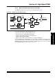
Equation 43-4: PERIOD, PHASEx and SPHASEx Register Value Calculation
PTPER STPER PHASEx SPHASEx,, ,
ACLK 8× DesiredPWMPeriod×
PWMInputClockPrescalerDivider PCLKDIV()
----------------------------------------------------------------------------------------------------------------------------
⎝⎠
⎛⎞
8–=
ACLK
REFCLK M1×
N
--------------------------------------=
ACLK
F
VCO
N
-------------=
Refer to Equation 43-1
Refer to Equation 43-2
(or)
Where,
REFCLK = FRC = 7.49 MHz (ACLKCON<6> = 1)
M1 = 16 Auxiliary PLL (ENAPLL = 1) Enabled
N = Post scaler ratio selected by the Auxiliary Post Scaler bits (APTSTSCLR<2:0>) in the
clock control register (ACLKCON<2:0>)
Note 1: Use the TUN<5:0> bits of OSCTUN register to tune the FRC clock frequency to
7.49 MHz to obtain a maximum PWM resolution of 1.04 ns. Refer to the “Oscillator
Configuration” section of the device data sheet for more information.