
Specifications


dsPIC33F/PIC24H Family Reference Manual
DS70323E-page 43-42 © 2008-2012 Microchip Technology Inc.
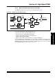
43.5.6 Time Base Synchronization
The master time base can be synchronized with the external synchronization signal through the
master time base synchronization signal (SYNCI1/SYNCI2/SYNCI3/SYNCI4). The
synchronization source (SYNCI1, SYNCI2, SYNCI3 and SYNCI4), can be selected using the
Synchronous Source Selection bits (SYNCSRC<1:0>) in the PWM Time Base Control register
(PTCON<5:4>). The Synchronize Input Polarity bit (SYNCPOL) in the PWM Time Base Control
register (PTCON<9>/STCON<9>), selects the rising or falling edge of the synchronization pulse,
which resets the timer (PMTMR/SMTMR). The External Synchronization feature can be enabled
or disabled with the External Time Base Synchronization Enable bit (SYNCEN) in the PWM Time
Base Control register (PTCON<7>/STCON<7>). The pulse width of the external synchronization
signal (SYNCI1/SYNCI2/SYNCI3/SYNCI4) should be more than 200 ns to ensure the reliable
detection by the master time base.
The external device can also be synchronized with the master time base using the
synchronization output signal (SYNCO). The SYNCO signal is generated when the
PTPER/STPER register resets the PMTMR/SMTMR timer. The SYNCO signal pulse is 12 T
CY
clocks wide (about 300 ns at 40 MIPS) to ensure other devices can sense the signal. The polarity
of the SYNCO signal is determined by the SYNCPOL bit in the PTCON/STCON register. The
SYNCO signal can be enabled or disabled by selecting the Primary Time Base Sync Enable bit
(SYNCOEN) in the PTCON/STCON register (PTCON<8>/STCON<8>).
The advantage of synchronization is that it ensures the beat frequencies are not generated when
multiple power controllers are in use. The configuration of synchronizing master time base with
external signal is shown in Example 43-5.
Example 43-5: Synchronizing Master Time Base with External Signal
The configuration of synchronizing external device with master time base is shown in
Example 43-6.
Example 43-6: Synchronizing External Device with Master Time Base
Note 1: The period of SYNCI pulse should be larger than the PWM period value.
2: The SYNCI pulse should be continuous with a minimum pulse width of 200 ns.
3: The PWM cycles are expected to be distorted for the first two SYNCI pulses.
4: The period value should be a multiple of 8 (Least Significant 3 bits set to ‘0’) for the
external synchronization to work in the Push-Pull mode.
5: When using external synchronization in the push-pull mode, the external
synchronization signal must be generated at twice the frequency of the desired
PWM frequency.
6: There is a delay from the input of a SYNC signal until the internal time base counter
is Reset. This will be approximately 30 ns.
7: The External Time Base Synchronization must not be used with phase shifted
PWM as the synchronization signal may not maintain the phase relationships
between the multiple PWM channels.
8: The External Time Base Synchronization cannot be used in Independent Time
Base mode.
/* Synchronizing Master Time base with External Signal */
PTCONbits.SYNCSRC = 0; /* Select SYNC1 input as synchronizing source */
PTCONbits.SYNCPOL = 0; /* Rising edge of SYNC1 resets the PWM Timer */
PTCONbits.SYNCEN = 1; /* Enable external synchronization */
/* Synchronizing external device with Master time base */
PTCONbits.SYNCPOL = 0; /* SYNCO output is active-high */
PTCONbits.SYNCOEN = 1; /* Enable SYNCO output */