
Specifications


© 2008-2012 Microchip Technology Inc. DS70323E-page 43-39
Section 43. High-Speed PWM
High-Speed PWM
43
43.5.4 Center-Aligned PWM
The center-aligned PWM waveforms as illustrated in Figure 43-6, align the PWM signals to a
reference point such that half of the PWM signal occurs before the reference point and the
remaining half of the signal occurs after the reference point. Center-aligned mode is enabled
when the Center-Aligned Mode Enable bit (CAM) in the PWM Control register (PWMCONx<2>)
is set.
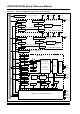
When operating in Center-aligned mode, the effective PWM period is twice the value that is
specified in the PWM Primary Phase Shift registers (PHASEx) because the independent time
base counter in the PWM generator is counting up and then counting down during the cycle. The
up/down count sequence doubles the effective PWM cycle period. This mode is used in many
motor control and uninterrupted power supply applications. The configuration of edge-aligned or
center-aligned mode selection is shown in Example 43-4. The typical application of
center-aligned PWM mode in UPS applications is illustrated in Figure 43-7.
Figure 43-6: Center-Aligned PWM Mode
Example 43-4: Edge-Aligned or Center-Aligned Mode Selection
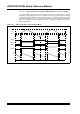
Figure 43-7: Center-Aligned PWM Mode in Power Inverter/UPS Applications
Note: Independent Time Base mode (ITB = 1) must be enabled to use Center-aligned
mode. If ITB = 0, the CAM bit (PWMCONx<2>) is ignored.
PHASEX
Local Time-Base Value
2 x Period
Period
0
PDC1
PDC2
PWM1H
PWM2H
/* Select Edge-Aligned PWM */
PWMCON1bits.CAM = 0; /* For Edge-Aligned Mode */
/* Select Center-Aligned PWM */
PWMCON1bits.CAM = 1; /* For Center-Aligned Mode */
PWMCON1bits.ITB = 1; /* Enable Independent Time Base */
VDC
S3
N
L
S1
S2
S4
+
–
PWM1H
PWM2H
PWM2L
PWM1L
I
L