
Specifications


dsPIC33F/PIC24H Family Reference Manual
DS70323E-page 43-38 © 2008-2012 Microchip Technology Inc.
Example 43-3: Using FVCO as the Auxiliary Clock Source
43.5.2 Time Base
Each PWM output in a PWM generator can use either the master time base or an independent
time base. The High-Speed PWM module input clock consists of the prescaler (divider)
options 1:1 to 1:64, which can be selected using the PWM Input Clock Prescaler (Divider) Select
bits (PCLKDIV<2:0>) in the PWM Generator Duty Cycle register (PTCON2<2:0>). This prescaler
affects all PWM time bases. The prescaled value will also reflect the PWM resolution, which
helps to reduce the power consumption of the High-Speed PWM module. The prescaled clock is
the input to the PWM clock control logic block. The maximum clock rate provides a duty cycle
and period resolution of 1.04 ns.
For example:
• If a prescaler option 1:2 is selected with ACLK = 120 MHz, the PWM duty cycle and period
resolution can be set at 2.08 ns. Therefore, the power consumption of the High-Speed
PWM module is reduced by approximately 50 percent of the maximum speed operation.
• If a prescaler option 1:4 is selected with ACLK = 120 MHz, the PWM duty cycle and period
resolution can be set at 4.16 ns. Therefore, the power consumption of the High-Speed
PWM module is reduced by approximately 75 percent of the maximum speed operation.
The High-Speed PWM module can operate in either the standard edge-aligned or center-aligned
time base.
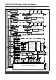
43.5.3 Standard Edge-Aligned PWM
Figure 43-5 illustrates the standard edge-aligned PWM waveforms. To create the edge-aligned
PWM, a timer or counter circuit counts upward from zero to a specified maximum value, called
the Period. Another register contains the duty cycle value, which is constantly compared with the
timer (period) value. When the timer or counter value is less than or equal to the duty cycle value,
the PWM output signal is asserted. When the timer value exceeds the duty cycle value, the PWM
signal is deasserted. When the timer is greater than or equal to the period value, the timer resets
itself, and the process repeats.
Figure 43-5: Standard Edge-Aligned PWM Mode
/* Assume Primary Oscillator is 8 MHz and FCY = 30 MHz. */
/* Therefore, FOSC = 60 MHz */
/* Setup for the Auxiliary clock to use Fvco as the source */
/* Fosc = Primary Oscillator * (PLLDIV / PLLPOST * PLLPRE) */
/* Fvco = Fosc * N2 */
/* Fosc = 60 MHz; N2 = 2; Fvco = 120 MHz; M = 30 */
/* Input to the Vco = 4 MHz; N1 = 2; Fin = 8 MHz */
ACLKCONbits.SELACLK = 0; /* Primary PLL (Fvco) provides the source
clock for the auxiliary clock divider */
/* Configuring PLL prescaler, PLL Post scaler, PLL divider */
PLLFBD = 28; /* M = 30 */
CLKDIVbits.PLLPOST = 0; /* N1 = 2 */
CLKDIVbits.PLLPRE = 0; /* N2 = 2 */
ACLKCONbits.APSTSCLR = 7; /* Divide Auxiliary click by 1 */
while (OSCCONbits.LOCK == 1);/* Wait for PLL to lock */
Period
PWM1H
T
ON
T
OFF
Period
Duty Cycle
0
Period
Timer
Value
Timer Resets
PWMxH
Value
Duty Cycle Match
New Duty Cycle