
Specifications


© 2008-2012 Microchip Technology Inc. DS70323E-page 43-35
Section 43. High-Speed PWM
High-Speed PWM
43
43.5 MODULE DESCRIPTION
43.5.1 PWM Clock Selection
The auxiliary clock generator must be used to generate the clock for the PWM module
independent of the system clock. The Primary Oscillator Clock (POSCCLK), Primary
Phase-Locked Loop (PLL) Output (FVCO), and Internal FRC Clock (FRCCLK) can be used with
an auxiliary PLL to obtain the Auxiliary Clock (ACLK). The auxiliary PLL consists of a fixed 16x
multiplication factor. Example 43-1 shows the configuration of auxiliary clock using FRC.
Example 43-2 shows the configuration of auxiliary clock using primary oscillator (P
OSC).
The Auxiliary Clock Control register (ACLKCON) selects the reference clock and enables the
auxiliary PLL and output dividers for obtaining the necessary auxiliary clock. Equation 43-1
provides the relationship between the Reference Clock (REFCLK) input frequency and the ACLK
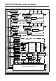
frequency. Figure 43-3 illustrates the oscillator system.
Figure 43-3: Oscillator System
÷N
ACLK
SELACLK
APSTSCLR<2:0>
To PWM/ADC
ENAPLL
APLL
x16
ASRCSEL
FRCSEL
POSCCLK
FRCCLK
÷N
ROSEL
RODIV<3:0>
REFCLKO
(3)
POSCCLK
Reference Clock Generation
Auxiliary Clock Generation
Note 1: Refer to the “Oscillator Configuration” chapter in the specific device data sheet for PLL details.
2: If the Oscillator is used with XT or HS modes, an external parallel resistor with the value of 1 MΩ must be connected.
3: REFCLK0 functionality is not available if the Primary Oscillator is used.
F
VCO
(1)
FOSC
Secondary Oscillator
LPOSCEN
SOSCO
SOSCI
Timer 1
OSC2
OSC1
Primary Oscillator
XTPLL, HSPLL,
XT, HS, EC
FRCDIV<2:0>
WDT, PWRT,
FSCM
FRCDIVN
SOSC
FRCDIV16
ECPLL, FRCPLL
NOSC<2:0> FNOSC<2:0>
Reset
FRC
Oscillator
LPRC
Oscillator
DOZE<2:0>
S3
S1
S2
S1/S3
S7
S6
FRC
LPRC
S0
S5
S4
÷16
Clock Switch
S7
Clock Fail
÷
2
TUNE bits
PLL
(1)
FCY
FOSC
FRCDIV
DOZE
FVCO
(1)
To ADC and
Auxiliary Clock
Generator
R
(2)
POSCMD<1:0>
POSCCLK
FP
(112 MHz - 120 MHz
max)