
Specifications


dsPIC33F/PIC24H Family Reference Manual
DS70323E-page 43-32 © 2008-2012 Microchip Technology Inc.
43.4 ARCHITECTURE OVERVIEW
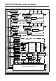
Figure 43-1 illustrates an architectural overview of the High-Speed PWM module and its
interconnection with the CPU and other peripherals.
Figure 43-1: High-Speed PWM Module Architectural Overview
CPU
Master Time Base
PWM
Generator 1
PWM
Generator 2
PWM
Generator 8
PWM
Generator 9
SYNCI1/2/3/4
SYNCO
PWM1H
PWM1L
PWM1 Interrupt
PWM2H
PWM2L
PWM2 Interrupt
PWM8H
PWM8L
PWM8 Interrupt
PWM9H
PWM9L
PWM9 Interrupt
Synchronization Signal
Data Bus
ADC Module
Fault and
Fault, Current-Limit
Synchronization Signal
Synchronization Signal
Synchronization Signal
Primary Trigger
Secondary Trigger
Special Event Trigger
Current Limit
and Dead-Time Compensation
Fault, Current-Limit
and Dead-Time Compensation
Fault, Current-Limit
and Dead-Time Compensation
PWM3 through PWM7
Secondary Special
Event Trigger
Primary Special
Event Trigger Interrupt
Secondary Special
Event Trigger Interrupt