
Specifications


dsPIC33F/PIC24H Family Reference Manual
DS70323E-page 43-26 © 2008-2012 Microchip Technology Inc.
bit 9 CLPOL: Current-limit Polarity bit for PWM Generator #
(1)
1 = The selected current-limit source is active-low
0 = The selected current-limit source is active-high
bit 8 CLMOD: Current-limit Mode Enable bit for PWM Generator #
1 = Current-limit mode is enabled
0 = Current-limit mode is disabled
bit 7-3 FLTSRC<4:0>: Fault Control Signal Source Select bits for PWM Generator #
(3,4)
For devices with remappable I/O:
11111 = Reserved
•
•
•
01000 = Reserved
00111 = Fault 8
00110 = Fault 7
•
•
•
00001 = Fault 2
00000 = Fault 1
For devices without remappable I/O:
11111 = Reserved
11110 = Fault 23
•
•
•
01001 = Fault 2
01000 = Fault 1
00111 = Reserved
00110 = Reserved
00101 = Reserved
00100 = Reserved
00011 = Analog Comparator 4
00010 = Analog Comparator 3
00001 = Analog Comparator 2
00000 = Analog Comparator 1
bit 2 FLTPOL: Fault Polarity bit for PWM Generator #
(1)
1 = The selected Fault source is active-low
0 = The selected Fault source is active-high
bit 1-0 FLTMOD<1:0>: Fault Mode bits for PWM Generator #
11 = Fault input is disabled
10 = Reserved
01 = The selected Fault source forces PWMxH and PWMxL pins to FLTDAT values (cycle)
00 = The selected Fault source forces PWMxH and PWMxL pins to FLTDAT values (latched condition)
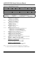
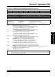
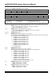
Register 43-22: FCLCONx: PWM Fault Current-Limit Control Register (Continued)
Note 1: These bits should be changed only when PTEN = 0.
2: When Independent Fault mode is enabled (IFLTMOD = 1), and Fault 1 is used for Current-limit mode
(CLSRC<4:0> = ‘b0000), the Fault Control Source Select bits (FLTSRC<4:0>) should be set to an
unused Fault source to prevent Fault 1 from disabling both the PWMxL and PWMxH outputs.
3: When Independent Fault mode is enabled (IFLTMOD = 1) and Fault 1 is used for Fault mode
(FLTSRC<4:0> = ‘b0000), the Current-limit Control Source Select bits (CLSRC<4:0>) should be set to an
unused current-limit source to prevent the current-limit source from disabling both the PWMxH and
PWMxL outputs.
4: Refer to the “Pin Diagrams” section in the specific device data sheet for more details on the number of
available Fault pins.