
Specifications


dsPIC33F/PIC24H Family Reference Manual
DS70323E-page 43-24 © 2008-2012 Microchip Technology Inc.
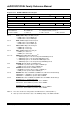
Register 43-20: TRIGx: PWM Primary Trigger Compare Value Register
R/W-0 R/W-0 R/W-0 R/W-0 R/W-0 R/W-0 R/W-0 R/W-0
TRGCMP<12:5>
bit 15 bit 8
R/W-0 R/W-0 R/W-0 R/W-0 R/W-0 U-0 U-0 U-0
TRGCMP<4:0>
— — —
bit 7 bit 0
Legend:
R = Readable bit W = Writable bit U = Unimplemented bit, read as ‘0’
-n = Value at POR ‘1’ = Bit is set ‘0’ = Bit is cleared x = Bit is unknown
bit 15-3 TRGCMP<12:0>: Trigger Control Value bits
When the primary PWM functions in local time base, this register contains the compare values that
can trigger the ADC module.
bit 2-0 Unimplemented: Read as ‘0’
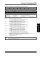
Register 43-21: STRIGx: PWM Secondary Trigger Compare Value Register
R/W-0 R/W-0 R/W-0 R/W-0 R/W-0 R/W-0 R/W-0 R/W-0
STRGCMP<12:5>
bit 15 bit 8
R/W-0 R/W-0 R/W-0 R/W-0 R/W-0 U-0 U-0 U-0
STRGCMP<4:0>
— — —
bit 7 bit 0
Legend:
R = Readable bit W = Writable bit U = Unimplemented bit, read as ‘0’
-n = Value at POR ‘1’ = Bit is set ‘0’ = Bit is cleared x = Bit is unknown
bit 15-3 STRGCMP<12:0>: Secondary Trigger Control Value bits
When the secondary PWM functions in local time base, this register contains the compare values that
can trigger the ADC module.
bit 2-0 Unimplemented: Read as ‘0’
Note: The STRIGx register cannot generate the PWM trigger interrupts.