
Specifications


© 2008-2012 Microchip Technology Inc. DS70323E-page 43-23
Section 43. High-Speed PWM
High-Speed PWM
43
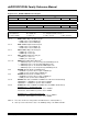
bit 3-2 CLDAT<1:0>: State for PWMxH and PWMxL Pins if CLMOD is Enabled bits
(2)
FCLCONx<15> = 0: Normal Fault mode
If current-limit active, then CLDAT<1> provides state for PWMxH
If current-limit active, then CLDAT<0> provides state for PWMxL
FCLCONx<
15> = 1: Independent Fault mode
CLDAT<1:0> is ignored
bit 1 SWAP: SWAP PWMxH and PWMxL Pins bit
1 = PWMxH output signal is connected to PWMxL pins; PWMxL output signal is connected to PWMxH
pins
0 = PWMxH and PWMxL pins are mapped to their respective pins
bit 0 OSYNC: Output Override Synchronization bit
1 = Output overrides through the OVRDAT<1:0> bits are synchronized to the PWM time base
0 = Output overrides through the OVRDAT<1:0> bits occur on next CPU clock boundary
Register 43-19: IOCONx: PWM I/O Control Register (Continued)
Note 1: These bits should not be changed after the PWM module is enabled (PTEN = 1).
2: State represents Active/Inactive state of the PWM depending on the POLH and POLL.