
Specifications


© 2008-2012 Microchip Technology Inc. DS70323E-page 43-15
Section 43. High-Speed PWM
High-Speed PWM
43
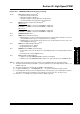
bit 7-6 DTC<1:0>: Dead Time Control bits
(3)
11 = Dead time Compensation mode
10 = Dead time function is disabled
01 = Negative dead time actively applied for all output modes
00 = Positive dead time actively applied for all output modes
bit 5 DTCP: Dead-Time Compensation Polarity bit
(3,6)
When set to ‘1’:
If DTCMPx = 0, PWMxL is shortened and PWMxH is lengthened.
If DTCMPx = 1, PWMxH is shortened and PWMxL is lengthened.
When set to ‘
0’:
If DTCMPx = 0, PWMxH is shortened and PWMxL is lengthened.
If DTCMPx = 1, PWMxL is shortened and PWMxH is lengthened.
bit 4 Unimplemented: Read as ‘0’
bit 3 MTBS: Master Time Base Select bit
1 = PWM generator uses the secondary master time base for synchronization and as the clock source
for the PWM generation logic (if secondary time base is available)
0 = PWM generator uses the primary master time base for synchronization and as the clock source
for the PWM generation logic
bit 2 CAM: Center-aligned Mode Enable bit
(2,3,5)
1 = Center-aligned mode is enabled
0 = Edge-aligned mode is enabled
bit 1 XPRES: External PWM Reset Control bit
(4)
1 = Current-limit source resets the time base for this PWM generator if it is in Independent Time Base
mode
0 = External pins do not affect PWM time base
bit 0 IUE: Immediate Update Enable bit
1 = Updates to the active MDC/PDCx/SDCx registers are immediate
0 = Updates to the active MDC/PDCx/SDCx registers are synchronized to the local PWM time base
Register 43-11: PWMCONx: PWM Control Register (Continued)
Note 1: Software must clear the interrupt status, and the corresponding IFS bit in the Interrupt Controller.
2: The Independent Time Base mode (ITB = 1) must be enabled to use Center-Aligned mode. If ITB = 0, the
CAM bit is ignored.
3: These bits should not be changed after the PWM is enabled (PTEN = 1).
4: Configure FCLCON
X<8> = 0 and PWMCONX<9> = 1, to operate in External Period Reset mode.
5: Center-aligned mode ignores the Least Significant 3 bits of the duty cycle, phase and dead time registers.
The highest CAM resolution available is 8.32 ns with the clock prescaler set to the fastest clock.
6: DTC<1:0> = 11 for DTCP to be effective; otherwise, DTCP is ignored.