
Specifications


dsPIC33F/PIC24H Family Reference Manual
DS70323E-page 43-110 © 2008-2012 Microchip Technology Inc.
43.21 REVISION HISTORY
Revision A (February 2008)
This is the initial released version of the document
Revision B (September 2008)
This revision incorporates the following updates:
• Equations:
- Updated Equation 43-4 in 43.6 “PWM Generator”
- Updated Equation 43-5 in 43.6.2.3 “Secondary Duty Cycle (SDCx)”
•Examples:
- Added an example for PWM Clock Code in 43.5.1 “PWM Clock Selection”
• Figures:
- Updated the labels in Figure 43-6
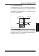
- Included new figure in 43.6.7 “Dead Time Resolution” (see Figure 43-15)
- Updated the fault source values in Figure 43-33 and Figure 43-36
• Headings:
- Added Auxiliary PLL as a new section (see 43.5.1 “PWM Clock Selection”)
in 43.5 “Module Description”
- The description for Dead Time Distortion has been corrected in 43.6.6 “Dead Time
Distortion”
- Added a new section on Dead-Time Insertion in Center-Aligned Mode
(see 43.6.8 “Dead Time Insertion in Center-Aligned Mode”
- Added a new sub-section for PWM Fault Generator (see 43.10.1 “PWM Fault
Generated by the Analog Comparator”) in 43.10 “PWM Fault Pins”
• Notes:
- Added a note on nominal input clock to the PWM in 43.5.1 “PWM Clock Selection”
- Added a note for the boundary conditions of the PWM resolution in the following
registers:
• MDC: PWM Master Duty Cycle Register (see Note 2 in Register 43-10)
• PDCx: PWM Generator Duty Cycle Register (see Note 2 in Register 43-12)
• SDCx: PWM Secondary Duty Cycle Register (see Note 2 in Register 43-13)
- Added a note for using Fault 1 for Current-Limit mode (CLSRC<4:0> = b0000) in
Register 43-22 (see Note 2)
- Added a note for configuring the auxiliary clock in 43.5.1 “PWM Clock Selection”
- Added a note on resetting the local time base in 43.16.5 “Current Reset PWM”
•Registers:
- The register descriptions for the PDCx: PWM Generator Duty Cycle Register and
SDCx: PWM Secondary Duty Cycle Register have been corrected
- The bit descriptions for bit 14-10 and bit 7-3 in Register 43-22 have been corrected
- Updated the bit field value of LEB as LEB<4:0> and LEB<6:5> in LEBCONx:
Leading-Edge Blanking Control Register (see Register 43-23)
- The Read/Write state for the bit 3 through bit 15 have been corrected in PWMCAPx:
Primary PWM Time Base Capture Register (see Register 43-27)
• Sections:
- The terms Complementary PWM Output Mode and Complementary PWM Mode have
been corrected as Complementary Mode in the entire document
- The terms Push-Pull PWM Output Mode and Push-Pull Mode have been corrected as
Push-Pull Mode in the entire document
• Changes to text and formatting were incorporated throughout the document