
Specifications


dsPIC33F/PIC24H Family Reference Manual
DS70323E-page 43-104 © 2008-2012 Microchip Technology Inc.
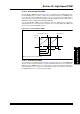
The scenario previously described can be prevented by using the flexible ADC triggering
features of the High-Speed PWM module. The Special Event Trigger, primary PWM trigger and
secondary PWM trigger can be used to generate an ADC conversion request with no software
overhead. This feature guarantees that the ADC conversion is triggered exactly when needed by
the circuitry. As the trigger is sent from the PWM to the ADC module directly in hardware, this
feature prevents any triggering delays caused by software.
The exact instant when the trigger is generated is determined by the SEVTCMP register for the
special event trigger, or the TRIGx and STRIGx registers for the PWM primary and secondary
triggers. For more information on the PWM trigger generation, refer to 43.7 “PWM Triggers”.
The High Speed 10-bit ADC provides multiple S&H circuits to allow simultaneous sampling. This
feature overcomes the problem of the ADC being busy at the sampling instant. For configuring
the trigger sources of ADC, refer to Section 44. “High-Speed 10-bit ADC” (DS70321).
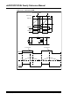
43.18.1.2 PWM CURRENT-LIMIT TRIGGERING OF ADC
The example of Figure 43-55 can also be implemented using Peak Current mode control. In this
method, the PWM is automatically truncated by the Current-Limit feature. While the current
limiting feature is capable of closely controlling the current, the position of the PWM falling edge
cannot be predicted. As a result, the Special Event Trigger, primary PWM and secondary PWM
triggers cannot be used to effectively trigger the ADC conversion.
This problem is mitigated by generating the ADC trigger signal directly using the PWM
current-limit source. Using this feature the ADC conversion is triggered at the exact instant as the
falling edge of the PWM pulse. Therefore, the peak current measurement can be made reliably
on every falling edge of the PWM signal.
43.18.2 PWM – Analog Comparator Interconnect
43.18.2.1 COMPARATOR CURRENT-LIMITS AND FAULTS
The Current-Limit and Fault functions can be used to limit any system parameter, including
current, voltage, power or temperature on a PWM cycle-by-cycle basis. The Analog Comparator
provides a unique way of truncating the PWM output directly in hardware.
The truncation of the PWM pulse is accomplished with no software intervention, and can be
programmed to respond to a variable threshold. The Analog Comparator can also be
programmed for inverted polarity selection. For example, the inverted polarity may be useful in
detecting an under-voltage condition or the absence of a system load.
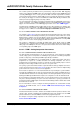
The cycle-by-cycle Current-Limit or Fault, in conjunction with the analog comparator can also be
used for peak current mode control. Figure 43-35 describes the control scheme for implementing
peak current mode control in a boost converter application.
Some instances require the use of the latched fault modes for protecting the system hardware.
The High-Speed PWM module provides the latched fault mode by which the PWM outputs are
shut down until the fault has been cleared by software. The Analog Comparator may be used for
latching the PWM outputs OFF when the input to the comparator exceeds the Fault threshold.
A good example for using latched fault mode is for short circuit protection. A short circuit event
may cause catastrophic damage to a power converter, and therefore, cycle-by-cycle Fault is not
preferred. Instead, the PWM outputs can be latched off indefinitely until the software detects that
the Fault has been cleared.
For more information on how to configure the Analog Comparator as a Current-limit or Fault
source for the PWM module, refer to 43.10.1 “PWM Fault Generated by the Analog
Comparator”.
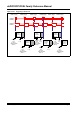
43.18.2.2 EXTERNAL PERIOD RESET MODE
The External Period Reset mode is similar to the Fault/Current-Limit operation, with the exact
opposite effect. Instead of shutting down the PWM output, this mode actually resets the PWM
period, and therefore restarts the PWM sooner than the programmed period.
An example of using the analog comparator for the external period reset mode is described
43.16.5 “Current Reset PWM”.