
Information


Table Of Contents
- TABLE 1: Silicon DEVREV Values (Continued)
- TABLE 2: Silicon Issue Summary (Continued)
- Silicon Errata Issues
- 1. Module: I/O Multiplexer
- 2. Module: CPU
- 3. Module: CPU
- 4. Module: PPS
- 5. Module: SPI
- 6. Module: SPI
- 7. Module: PWM
- 8. Module: PWM
- 9. Module: Power System
- 10. Module: Reserved
- 11. Module: ECAN™
- 12. Module: ECAN
- 13. Module: USB
- 14. Module: USB
- 15. Module: DMA
- 16. Module: UART
- 17. Module: UART
- 18. Module: UART
- 19. Module: I2C™
- 20. Module: ADC
- 21. Module: PMP
- 22. Module: Flash Memory
- 23. Module: Flash Memory
- 24. Module: Power System
- 25. Module: PWM
- 26. Module: QEI
- 27. Module: QEI
- 28. Module: CPU
- 29. Module: PWM
- 30. Module: ECAN
- 31. Module: Auxiliary Flash
- 32. Module: Auxiliary Flash
- 33. Module: Output Compare
- 34. Module: ADC
- Data Sheet Clarifications
- Appendix A: Revision History
© 2011-2012 Microchip Technology Inc. DS80526C-page 7
dsPIC33EPXXX(GP/MC/MU)806/810/814 and PIC24EPXXX(GP/GU)810/814
7. Module: PWM
When dead time compensation is enabled
(PWMCONx<DTC> = 11) in Edge-Aligned mode
(PWMCONx<CAM> = 0), the setting of the
DTCP<1:0> bits (PWMCONx<7:6>) and the
external signal DTCMPx, determine whether the
DTRx register is added to or subtracted from the
duty cycle specified by the PDCx or MDC
registers.
When DTR is being subtracted from the duty cycle,
the resulting duty cycle will be 0% if the
programmed duty cycle, minus two times the DTR
value, is less than ‘0’.
Duty Cycle = 0% when (PDCx – 2 DTR)
< 0 if MDCS = 0 (PWMCONx<8>)
or
(MDC – 2 DTR) < 0 if MDCS = 1
(PWMCONx<8>)
When DTR is being added to the duty cycle, the
resulting duty cycle will be 100% if the
programmed duty cycle, plus two times the DTR
register, is greater than the period.
Duty Cycle = 100% when (PDCx + 2 DTR)
≥ Period if MDCS = 0 (PWMCONx<8>)
or
(MDC + 2 DTR) ≥ Period if MDCS = 1
(PWMCONx<8>)
The period is specified by the PTPER, STPER or
PHASEx registers, depending on the ITB
(PWMCON<9>) and MTBS (PWMCONx<3>) bit
settings.
Work around
If using dead time compensation, do not use duty
cycle values that are less than two times the DTR
value or that are greater than or equal to the period
less two times the DTR value.
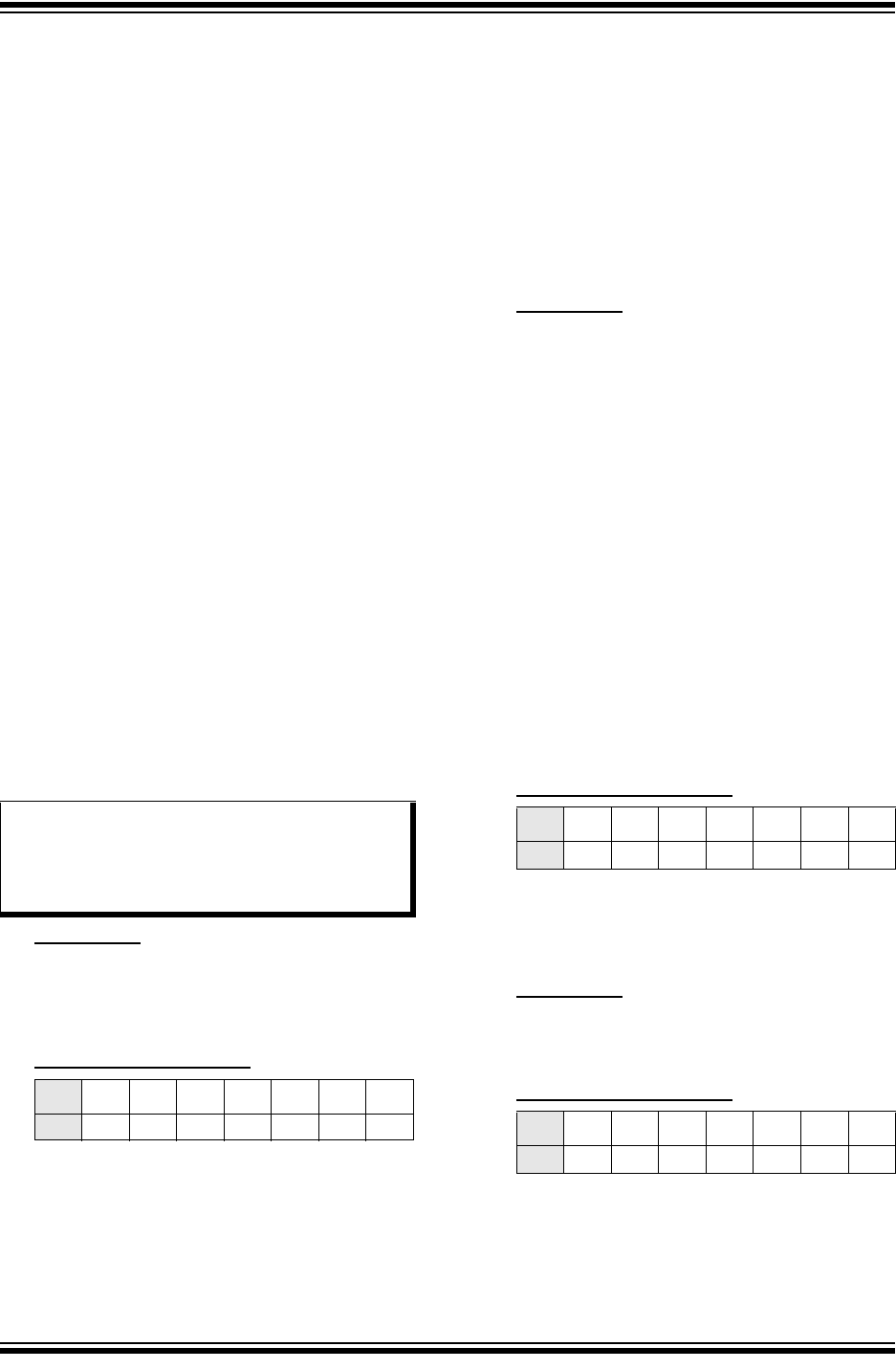
Affected Silicon Revisions
8. Module: PWM
When dead time compensation is enabled
(PWMCONx<DTC> = 11) in Center-Aligned mode
(PWMCONx<CAM> = 1), the dead time, as
specified in the ALTDTRx register, is not being
applied to the PWMxH output. The leading and
trailing edges of the PWMxL output are extended
by one-half the value of the ALTDTRx register, but
the PWMxH leading and trailing edges are
unaffected.
Work around
Using the values from Section 14. “High-Speed
PWM” (DS70645), adjust the PWM parameters as
follows:
• Subtract one-half of the ALTDTR dead time
from PDCx
• Use twice the value for ALTDTR. For example:
- Frequency of 60 kHz, duty cycle of 50%
- Desired dead time of 833 ns and dead time
compensation of 833 ns
Using the specified values from Section 14.
“High-Speed PWM” (DS70645):
• PHASEx = 1000
• PDCx = 500
• ALTDTR = 833 ns/8.33 ns = 100
• DTR = (833 ns/8.33 ns)/2 = 50
Applying the work around:
• ALTDTR = 2 * 100 = 200
• PDCx = PDCx – 25 = 475
Affected Silicon Revisions
9. Module: Power System
For this version of silicon, the Brown-out Reset
(BOR) must always be enabled.
Work around
Do not disable the BOR by setting BOREN = 0
(FPOR<3>) or by setting SBOREN = 0
(RCON<13>).
Affected Silicon Revisions
Note: The dead time values, as specified in the
ALTDTRx register, are not part of the
equations shown above, and are still
applied when the duty cycle is not forced
to 0% or 100%.
B1
X
B1
X
B1
X