
Information


Table Of Contents
- TABLE 1: Silicon DEVREV Values (Continued)
- TABLE 2: Silicon Issue Summary (Continued)
- Silicon Errata Issues
- 1. Module: I/O Multiplexer
- 2. Module: CPU
- 3. Module: CPU
- 4. Module: PPS
- 5. Module: SPI
- 6. Module: SPI
- 7. Module: PWM
- 8. Module: PWM
- 9. Module: Power System
- 10. Module: Reserved
- 11. Module: ECAN™
- 12. Module: ECAN
- 13. Module: USB
- 14. Module: USB
- 15. Module: DMA
- 16. Module: UART
- 17. Module: UART
- 18. Module: UART
- 19. Module: I2C™
- 20. Module: ADC
- 21. Module: PMP
- 22. Module: Flash Memory
- 23. Module: Flash Memory
- 24. Module: Power System
- 25. Module: PWM
- 26. Module: QEI
- 27. Module: QEI
- 28. Module: CPU
- 29. Module: PWM
- 30. Module: ECAN
- 31. Module: Auxiliary Flash
- 32. Module: Auxiliary Flash
- 33. Module: Output Compare
- 34. Module: ADC
- Data Sheet Clarifications
- Appendix A: Revision History
dsPIC33EPXXX(GP/MC/MU)806/810/814 and PIC24EPXXX(GP/GU)810/814
DS80526C-page 6 © 2011-2012 Microchip Technology Inc.
3. Module: CPU
When using the Signed 32-by-16-bit Division
instruction, div.sd, the overflow bit does not
always get set when an overflow occurs.
Work around
Test for and handle overflow conditions outside of
the div.sd instruction.
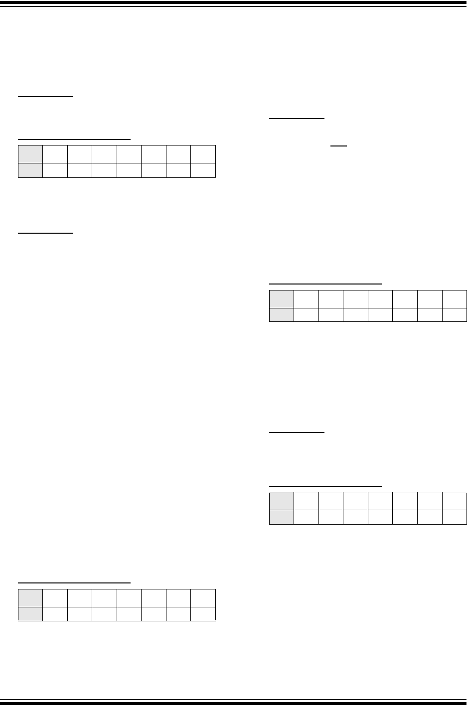
Affected Silicon Revisions
4. Module: PPS
Virtual pin remapping does not work.
Work around
Virtual remapping applies to comparator outputs
and the QEI Home and Index functions:
1. Comparator outputs can be connected to a
peripheral input by mapping both the com-
parator output and the peripheral input to an
unused physical pin using the peripheral
pin select feature.
The following example assumes that there is
no connection to the RP127/RG15 pin on the
device. The following statements connect
Comparator Output 1 to Input Capture IC1
using RP127.
RPINR7bits.IC1R = 127;
/*assign Input Capture 1 to RP127*/
RPOR15bits.RP127R = 0b011000;
/*assign RP127 to Comparator Output 1*/
2. The FCLCONx register can be used to map
comparator outputs to PWM fault inputs
without the use of virtual remapping.
The following statement will connect
Comparator 1 output to Fault Control Signal
Source for PWM 1.
FCLCON1bits.FLTSRC = 8;
/* value of 0b01000 selects Comp. 1 */
3. FHOMEx and FINDXx are not accessible,
making the digital filter in the QEI module
unusable for any other peripheral besides
the QEI. There is no work around.
Affected Silicon Revisions
5. Module: SPI
When using the frame sync pulse output feature
(SPIxCON2<FRMEN> = 1) in Master Mode
(SPIxCON2<SPIFSD> = 0), the frame sync pulse
is not being generated with an active low pulse
(SPIxCON2<FRMPOL> = 0).
Work around
The SS pin is used as the frame sync pulse when
the frame sync pulse output feature is used.
Mapping the SSx input function and output
function to the same pad using the PPS feature
resolves this issue.
The following code example assigns SPI1 SS
input and SPI1 SS output to RP118.
RPINR21bits.SS1R = 118;
/* assign the SPI1 Slave Select Input to
RP118 */
RPOR13bits.RP118R = 0b000111;
/* assign peripheral output function SPI1
to RP118 */
Affected Silicon Revisions
6. Module: SPI
When in SPI Slave mode (SPIxCON1<MSTEN> =
0) and using the frame sync pulse output feature
(SPIxCON2<FRMEN> = 1) in Slave Mode
(SPIxCON2<SPIFSD> = 0), the Frame Sync
Pulse Edge Select bit must be set to ‘0’
(SPIxCON2 <FRMDLY> = 0)
Work around
There is no work around. The Frame Sync Pulse
Edge Select bit cannot be set to produce a Frame
sync pulse that coincides with the first bit clock.
Affected Silicon Revisions
B1
X
B1
X
B1
X
B1
X