
Datasheet


dsPIC33EPXXXGP50X, dsPIC33EPXXXMC20X/50X AND PIC24EPXXXGP/MC20X
DS70000657H-page 516 2011-2013 Microchip Technology Inc.
Revision H (August 2013)
This revision includes minor typographical and
formatting changes throughout the text.
Other major changes are referenced by their respective
section in Table A-6.
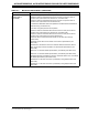
TABLE A-6: MAJOR SECTION UPDATES
Section Name Update Description
Cover Section • Adds Peripheral Pin Select (PPS) to allow Digital Function Remapping and Change
Notification Interrupts to Input/Output section
• Adds heading information to 64-Pin TQFP
Section 4.0 “Memory
Organization”
• Corrects Reset values for ANSELE, TRISF, TRISC, ANSELC and TRISA
• Corrects address range from 0x2FFF to 0x7FFF
• Corrects DSRPAG and DSWPAG (now 3 hex digits)
• Changes Call Stack Frame from <15:1> to PC<15:0>
• Word length in Figure 4-20 is changed to 50 words for clarity
Section 5.0 “Flash Program
Memory”
•
Corrects descriptions of NVM registers
Section 9.0 “Oscillator
Configuration”
• Removes resistor from Figure 9-1
• Adds Fast RC Oscillator with Divide-by-16 (FRCDIV16) row to Table 9-1
• Removes incorrect information from ROI bit in Register 9-2
Section 14.0 “Input Capture” • Changes 31 user-selectable Trigger/Sync interrupts to 19 user-selectable Trigger/
Sync interrupts
• Corrects ICTSEL<12:10> bits (now ICTSEL<2:0>)
Section 17.0 “Quadrature
Encoder Interface (QEI)
Module
(dsPIC33EPXXXMC20X/50X
and PIC24EPXXXMC20X
Devices Only)”
• Corrects QCAPEN bit description
Section 19.0 “Inter-
Integrated Circuit™ (I
2
C™)”
• Adds note to clarify that 100kbit/sec operation of I
2
C is not possible at high processor
speeds
Section 22.0 “Charge Time
Measurement Unit (CTMU)”
• Clarifies Figure 22-1 to accurately reflect peripheral behavior
Section 23.0 “10-Bit/12-Bit
Analog-to-Digital Converter
(ADC)”
•Correct Figure 23-1 (changes CH123x to CH123Sx)
Section 24.0 “Peripheral
Trigger Generator (PTG)
Module”
• Adds footnote to Register 24-1 (In order to operate with CVRSS=1, at least one of the
comparator modules must be enabled.
Section 25.0 “Op Amp/
Comparator Module”
• Adds note to Figure 25-3 (In order to operate with CVRSS=1, at least one of the
comparator modules must be enabled)
• Adds footnote to Register 25-2 (COE is not available when OPMODE
(CMxCON<10>) = 1)
Section 27.0 “Special
Features”
• Corrects the bit description for FNOSC<2:0>
Section 30.0 “Electrical
Characteristics”
• Corrects 512K part power-down currents based on test data
• Corrects WDT timing limits based on LPRC oscillator tolerance
Section 31.0 “High-
Temperature Electrical
Characteristics”
•Adds Table 31- 5 (DC Characteristics: Idle Current (IIDLE)