
Datasheet


© 2010 Microchip Technology Inc. DS70135G-page 103
dsPIC30F4011/4012
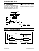
15.7.1 DEAD-TIME GENERATORS
Each complementary output pair for the PWM module
has a 6-bit down counter that is used to produce the
dead-time insertion. As shown in Figure 15-4, each
dead-time unit has a rising and falling edge detector
connected to the duty cycle comparison output.
15.7.2 DEAD-TIME RANGES
The amount of dead time provided by the dead-time
unit is selected by specifying the input clock prescaler
value and a 6-bit unsigned value.
Four input clock prescaler selections have been
provided to allow a suitable range of dead time based
on the device operating frequency. The dead-time
clock prescaler values are selected using the
DTAPS<1:0> control bits in the DTCON1 SFR. One of
four clock prescaler options (T
CY, 2 TCY, 4 TCY or 8 TCY)
may be selected.
After the prescaler value is selected, the dead time is
adjusted by loading 6-bit unsigned values into the
DTCON1 SFR.
The dead-time unit prescaler is cleared on the following
events:
• On a load of the down timer due to a duty cycle
comparison edge event.
• On a write to the DTCON1 register.
• On any device Reset.
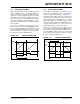
FIGURE 15-4: DEAD-TIME TIMING DIAGRAM
Note: The user should not modify the DTCON1
register value while the PWM module is
operating (PTEN = 1). Unexpected results
may occur.
Duty Cycle Generator
PWMxH
PWMxL
Dead-Time A (Active) Dead-Time A (Inactive)