
Datasheet


© 2006 Microchip Technology Inc. Preliminary DS70178C-page 209
dsPIC30F1010/202X
ply loading the Reset address into the oscillator fail
trap vector. In this event, the CF (Clock Fail) status bit
(OSCCON<3>) is also set whenever a clock failure is
recognized.
In the event of a clock failure, the WDT is unaffected
and continues to run on the LPRC clock.
If the oscillator has a very slow start-up time coming
out of POR or Sleep, it is possible that the PWRT timer
will expire before the oscillator has started. In such
cases, the FSCM will be activated and the FSCM will
initiate a clock failure trap, and the COSC<2:0> bits
are loaded with FRC oscillator selection. This will
effectively shut off the original oscillator that was trying
to start.
The user may detect this situation and restart the
oscillator in the clock fail trap, ISR.
Upon a clock failure detection, the FSCM module will
initiate a clock switch to the FRC oscillator as follows:
1. The COSC bits (OSCCON<14:12>) are loaded
with the FRC oscillator selection value
2. CF bit is set (OSCCON<3>)
3. OSWEN control bit (OSCCON<0>) is cleared
For the purpose of clock switching, the clock sources
are sectioned into two groups:
1. Primary
2. Internal FRC
The user can switch between these functional groups,
but cannot switch between options within a group. If the
primary group is selected, then the choice within the
group is always determined by the FNOSC<1:0>
Configuration bits.
The OSCCON register holds the control and status bits
related to clock switching. If Configuration bits
FCKSM<1:0> = 1x, then the clock switching and Fail-
Safe Clock Monitor functions are disabled. This is the
default Configuration bit setting.
If clock switching is disabled, then the FNOSC<1:0>
and POSCMD<1:0> bits directly control the oscillator
selection and the COSC<2:0> bits do not control the
clock selection. However, these bits will reflect the
clock source selection.
18.7 Reset
The PIC18F1220/1320 differentiates between
various kinds of Reset:
a) Power-on Reset (POR)
b) MCLR
Reset during normal operation
c) MCLR
Reset during Sleep
d) Watchdog Timer (WDT) Reset (during normal
operation)
e) RESET Instruction
f) Reset cause by trap lock-up (TRAPR)
g) Reset caused by illegal opcode, or by using an
uninitialized W register as an Address Pointer
(IOPUWR)
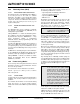
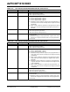
Different registers are affected in different ways by var-
ious Reset conditions. Most registers are not affected
by a WDT wake-up, since this is viewed as the resump-
tion of normal operation. Status bits from the RCON
register are set or cleared differently in different Reset
situations, as indicated in Table 18-3. These bits are
used in software to determine the nature of the Reset.
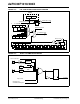
A block diagram of the on-chip Reset circuit is shown in
Figure 18-7.
A MCLR
noise filter is provided in the MCLR Reset
path. The filter detects and ignores small pulses.
Internally generated Resets do not drive MCLR pin low.
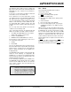
Note: The application should not attempt to
switch to a clock frequency lower than 100
KHz when the Fail-Safe Clock Monitor is
enabled. If clock switching is performed,
the device may generate an oscillator fail
trap and switch to the Fast RC oscillator.