
Datasheet


© 2006 Microchip Technology Inc. Preliminary DS70178C-page 193
dsPIC30F1010/202X
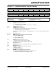
REGISTER 17-1: COMPARATOR CONTROL REGISTERX (CMPCONx)
R/W-0 U-0 R/W-0 U-0 U-0 U-0 U-0 U-0
CMPON
— CMPSIDL — — — — —
bit 15 bit 8
R/W-0 R/W-0 R/W-0 U-0 R/W-0 U-0 R/W-0 R/W-0
INSEL<1:0> EXTREF — CMPSTAT — CMPPOL RANGE
bit 7 bit 0
Legend:
R = Readable bit W = Writable bit U = Unimplemented bit, read as ‘0’
-n = Value at POR ‘1’ = Bit is set ‘0’ = Bit is cleared x = Bit is unknown
bit 15 CMPON: A/D Operating Mode bit
1 = Comparator module is enabled
0 = Comparator module is disabled (reduces power consumption)
bit 14 Unimplemented: Read as ‘0’
bit 13 CMPSIDL: Stop in Idle Mode bit
1 = Discontinue module operation when device enters Idle mode.
0 = Continue module operation in Idle mode.
If a device has multiple comparators, any CMPSIDL bit set to ‘1’ disables ALL comparators while in
Idle mode.
bit 12-8 Reserved: Read as ‘0’
bit 7-6 INSEL<1:0>: Input Source Select for Comparator bits
00 = Select CMPxA input pin
01 = Select CMPxB input pin
10 = Select CMPxC input pin
11 = Select CMPxD input pin
bit 5 EXTREF: Enable External Reference bit
1 = External source provides reference to DAC
0 = Internal reference sources provide source to DAC
bit 4 Reserved: Read as ‘0’
bit 3 CMPSTAT: Current State of Comparator Output Including CMPPOL Selection bit
bit 2 Reserved: Read as ‘0’
bit 1 CMPPOL: Comparator Output Polarity Control bit
1 = Output is inverted
0 = Output is non inverted
bit 0 RANGE: Selects DAC Output Voltage Range bit
1 = High Range: Max DAC value = AV
DD / 2, 2.5V @ 5 volt VDD
0 = Low Range: Max DAC value = INTREF, 1.2V ±1%