
Datasheet


© 2006 Microchip Technology Inc. Preliminary DS70178C-page 191
dsPIC30F1010/202X
17.0 SMPS COMPARATOR MODULE
The dsPIC30F SMPS Comparator module monitors
current and/or voltage transients that may be too fast
for the CPU and ADC to capture.
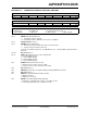
17.1 Features Overview
• 16 comparator inputs
• 10-bit DAC provides reference
• Programmable output polarity
• Interrupt generation capability
• Selectable Input sources
• DAC has three ranges of operation:
-AV
DD / 2
- Internal Reference 1.2V 1%
- External Reference < (AV
DD - 1.6V)
• ADC sample and convert trigger capability
• Can be disabled to reduce power consumption
• Functional support for PWM Module:
- PWM Duty Cycle Control
- PWM Period Control
- PWM Fault Detect
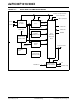
FIGURE 17-1: COMPARATOR MODULE BLOCK DIAGRAM
17.2 Module Applications
This module provides a means for the SMPS dsPIC
DSC devices to monitor voltage and currents in a
power conversion application. The ability to detect
transient conditions and stimulate the dsPIC DSC pro-
cessor and/or peripherals without requiring the proces-
sor and ADC to constantly monitor voltages or currents
frees the dsPIC DSC to perform other tasks.
The Comparator module has a high-speed comparator
and an associated 10-bit DAC that provides a pro-
grammable reference voltage to one input of the com-
parator. The polarity of the comparator output is user
programmable. The output of the module can be used
in the following modes:
• Generate an interrupt
• Trigger an ADC sample and convert process
• Truncate the PWM signal (current limit)
• Truncate the PWM period (current minimum)
• Disable the PWM outputs (Fault-latch)
The output of the Comparator module may be used in
multiple modes at the same time, such as: (1) gener-
ate an interrupt, (2) have the ADC take a sample and
convert it and (3) truncate the PWM output in
response to a voltage being detected beyond its
expected value.
The Comparator module can also be used to wake-up
the system from Sleep or Idle mode when the analog
input voltage exceeds the programmed threshold
voltage.
Note: This data sheet summarizes features of this group
of dsPIC30F devices and is not intended to be a complete
reference source. For more information on the CPU,
peripherals, register descriptions and general device
functionality, refer to the “dsPIC30F Family Reference
Manual” (DS70046).
CMP
x
A*
CMP
x
C*
DAC
CMPPOL
0
1
AVDD/2
INTREF
AVSS
M
U
X
CMREF
CMP
x
*
RANGE
INSEL<1:0>
10
Trigger to PWM
Interrupt Request
CMP
x
B*
CMP
x
D*
Glitch Filter Pulse Generator
Status
EXTREF
M
U
X
* x=1, 2, 3 & 4