
Datasheet


dsPIC30F1010/202X
DS70178C-page 184 Preliminary © 2006 Microchip Technology Inc.
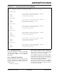
Example 16-1 shows a code sequence for using the
ADBASE register to implement ADC Input Pair Inter-
rupt Handling. When the ADBASE register is read, it
contains the sum of the base address of the jump table
and the encoded ADC channel pair number left shifted
by 2 bits.
For example, if ADBASE is initialized with a value of
0x0360, a channel pair 1 interrupt would cause an
ADBASE read value of 0x0364 (0x360 +
0b00000100). A channel pair 3 interrupt would cause
an ADBASE read value of 0x036C (0x360 +
0b00001100).
EXAMPLE 16-1: ADC BASE REGISTER CODE
; Initialize and enable the ADC interrupt
MOV #handle(JMP_TBL),W0 ; Load the base address of the ISR Jump
MOV WO, ADBASE ; table in ADBASE.
BSET IPC2,#12 ; Set up the interrupt priority
BSET IPC2,#13
BSET IPC2,#14
BCLR IFS0,#11 ; Clear any pending interrupts
BCLR ADSTAT ; Clear the ADC pair interrupts as well
BSET IEC0,#11 ; Enable the interrupt
; Code to Initialize the rest of the ADC registers
...
...
...
; ADC Interrupt Handler
__ADCInterrupt:
PUSH.S ; Save WO-W3 and SR registers
BCLR IFSO,#11 ; Clear the interrupt
MOV ADBASE, W0 ; ADBASE contains the encoded jump address
GOTO W0 ; within JMP_TBL
; Here's the Jump Table
; Note: It is important to clear the individual IRQ flags in the ADC AFTER the IRQ flags
in the interrupt controller. Failure to do so may cause interrupt requests to be lost
JMP_TBL:
BCLR ADSTAT,#0 ; Clear the IRQ flag in the ADC
BRA ADC_PAIR0_PROC ; Actual Pair 0 Conversion Interrupt Handler
BCLR ADSTAT,#1 ; Clear the IRQ flag in the ADC
BRA ADC_PAIR1_PROC ; Actual Pair 1 Conversion Interrupt Handler
BCLR ADSTAT,#2 ; Clear the IRQ flag in the ADC
BRA ADC_PAIR2_PROC ; Actual Pair 2 Conversion Interrupt Handler
BCLR ADSTAT,#3 ; Clear the IRQ flag in the ADC
BRA ADC_PAIR3_PROC ; Actual Pair 3 Conversion Interrupt Handler
BCLR ADSTAT,#4 ; Clear the IRQ flag in the ADC
BRA ADC_PAIR4_PROC ; Actual Pair 4 Conversion Interrupt Handler