
Datasheet


dsPIC30F1010/202X
DS70178C-page 164 Preliminary © 2006 Microchip Technology Inc.
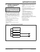
REGISTER 15-1: U1MODE: UART1 MODE REGISTER
R/W-0 U-0 R/W-0 R/W-0 U-0 R/W-0 U-0 U-0
UARTEN — USIDL IREN —ALTIO— —
bit 15 bit 8
R/W-0 HC R/W-0 R/W-0 HC R/W-0 R/W-0 R/W-0 R/W-0 R/W-0
WAKE LPBACK ABAUD RXINV BRGH PDSEL1 PDSEL0 STSEL
bit 7 bit 0
Legend: U = Unimplemented bit, read as ‘0’
R = Readable bit W = Writable bit HC = Hardware Cleared HS = Hardware Select
-n = Value at POR ‘1’ = Bit is set ‘0’ = Bit is cleared x = Bit is unknown
bit 15 UARTEN: UART1 Enable bit
1
= UART1 enabled; all UART1 pins are controlled by UART1 as defined by UEN<1:0>
0
= UART1 disabled; all UART1 pins are controlled by PORT latches; UART1 power consumption minimal
bit 14 Unimplemented: Read as ‘0’
bit 13 USIDL: Stop in Idle Mode bit
1 = Discontinue module operation when device enters Idle mode
0 = Continue module operation in Idle mode
bit 12 IREN: IrDA Encoder and Decoder Enable bit
1 = IrDA encoder and decoder enabled
0 = IrDA encoder and decoder disabled
Note: This feature is only available for the 16x BRG mode (BRGH = 0).
bit 11 Unimplemented: Read as ‘0’
bit 10 ALTIO: UART Alternate I/O Selection bit
1 = UART communicates using U1ATX and U1ARX I/O pins
0 = UART communicates using U1TX and U1RX I/O pins.
bit 9-8 Unimplemented: Read as ‘0’
bit 7 WAKE: Wake-up on Start bit Detect During Sleep Mode Enable bit
1 = UART1 will continue to sample the U1RX pin; interrupt generated on falling edge, bit cleared in
hardware on following rising edge
0 = No wake-up enabled
bit 6 LPBACK: UART1 Loopback Mode Select bit
1 = Enable Loopback mode
0 = Loopback mode is disabled
bit 5 ABAUD: Auto-Baud Enable bit
1 = Enable baud rate measurement on the next character – requires reception of a Sync field (55h);
cleared in hardware upon completion
0 = Baud rate measurement disabled or completed
bit 4 RXINV: Receive Polarity Inversion bit
1 = U1RX Idle state is ‘0’
0 = U1RX Idle state is ‘1’
bit 3 BRGH: High Baud Rate Enable bit
1 = BRG generates 4 clocks per bit period (4x Baud Clock, High-Speed mode)
0 = BRG generates 16 clocks per bit period (16x Baud Clock, Standard mode)