
Datasheet


dsPIC30F1010/202X
DS70178C-page 138 Preliminary © 2006 Microchip Technology Inc.
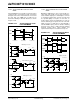
12.34.3 APPLICATION OF PUSH-PULL PWM
MODE
Push-Pull PWM mode is typically used in transformer
coupled circuits to ensure that no net DC currents flow
through the transformer. Push-Pull mode ensures that
the same duty cycle PWM pulse is applied to the
transformer windings in alternate directions, as shown
in Figure 12-24.
FIGURE 12-24: APPLICATIONS OF PUSH-
PULL PWM MODE
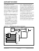
12.34.4 APPLICATION OF MULTI-PHASE PWM
MODE
Multi-Phase PWM mode is often used in DC/DC con-
verters that must handle very fast load current tran-
sients and fit into tight spaces. A multi-phase converter
is essentially a parallel array of buck converters that
are operated slightly out of phase of each other, as
shown in Figure 12-25. The multiple phases create an
effective switching speed equal to the sum of the indi-
vidual converters. If a single phase is operating with a
333 KHz PWM frequency, then the effective switching
frequency for the circuit is 1 MHz. This high switching
frequency greatly reduces output capacitor size
requirements and improves load transient response.
FIGURE 12-25: APPLICATIONS OF MULTI-
PHASE PWM MODE
+
T1
VOUT
Half Bridge Converter
+V
IN
PWM1H
PWM1L
+
+
L1
PWM1H
PWM1L
T
ON
TOFF
TON
TOFF
Period Period
Dead Time Dead Time Dead Time
T1
+
+VIN
PWM1H
PWM1L
Push-Pull Buck Converter
L1
V
OUT
PWH1H
PWH1L
PWH1L
PWH1H
+V
IN
T1 L1
V
OUT
Full Bridge Converter
+
+
+VIN
PWM1H PWM2H PWM3H
L1
L2
L3
PWM1L PWM1L PWM1L
V
OUT
Converter
Multiphase DC/DC
PWM1H
PWM1L
PWM2H
PWM2L
PWM3H
PWM3L