
Datasheet


dsPIC30F1010/202X
DS70178C-page 130 Preliminary © 2006 Microchip Technology Inc.
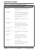
EXAMPLE 12-1: CODE EXAMPLE FOR CONFIGURING PWM CHANNEL 1
.
mov #0x0400, w0 ; PWM Module is disabled, continue operation in
mov w0, PTCON ; idle mode, special event interrupt disabled,
; immediate period updates enabled, no external
; synchronization
; Set the PWM Period
mov #0x094D, w0 ; Select period to be approximately 2.5usec
mov w0, PTPER ; PLL Frequency is ~480MHz. This equates to a
; clocke period of 2.1nsec. The PWM period and
; duty cycle registers are triggered on both +ve
; and -ve edges of the PLL clock. Therefore,
; one count of the PTPER and PDCx registers
; equals 1.05nsec.
; So, to achieve a PWM period of 2.5usec, we
; choose PTPER = 0x094D
mov #0x0000, w0 ; no phase shift for this PWM Channel
mov w0, PHASE1 ; This register is used for generating variable
; phase PWM
; Select individual Duty Cycle Control
mov #0x0001, w0 ; Fault interrupt disabled, Current Limit
mov w0, PWMCON1 ; interrupt disabled, trigger interrupt,
; disabled, Primary time base provides timing,
; DC1 provides duty cycle information, positive
; dead time applied, no external PWM reset,
; Enable immediate duty cycle updates
; Code for PWM Current Limit and Fault Inputs
mov #0x0003, w0
mov w0, FCLCON1 ; Disable current limit and fault inputs
; Code for PWM Output Control
mov #0xC000, w0 ; PWM1H and PWM1L is controlled by PWM module
mov w0, IOCON1 ; Output polarities are active high, override
; disabled
; Duty Cycle Setting
mov #0x04A6, w0 ; To achieve a duty cycle of 50%, we choose
mov w0, PDC1 ; the PDC1 value = 0.5*(PWM Period)
; The ON time for the PWM = 1.25usec
; The Duty Cycle Register will provide
; positive duty cycle to the PWMxH outputs
; when output polarities are active high
; (see IOCON1 register)
; Dead Time Setting
mov #0x0040, w0 ; Dead time ~ 67nsec
mov w0, DTR1 ; Hex(40) = decimal(64)
; So, Dead time = 64*1.05nsec = 67.2nsec
; Note that the last 2 bits are unimplemented,
; therefore the dead time register can achieve a
; a resolution of about 4nsec.
mov w0, ALTDTR1 ; Load the same value in ALTDTR1 register
bset PTCON, #15 ; turn ON PWM module
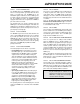
Note: This code example does not illustrate configuration of various fault modes for the PWM module.
It is intended as a quick start guide for setting up the PWM Module.