
Datasheet


© 2006 Microchip Technology Inc. Preliminary DS70178C-page 127
dsPIC30F1010/202X
12.14 Dead-Time Generation
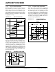
Dead time refers to a programmable period of time,
specified by the Dead-Time Register (DTR) or the ALT-
DTR register, which prevent a PWM output from being
asserted until its complementary PWM signal has been
deasserted for the specified time. Figure 12-15 shows
the insertion of dead time in a complementary pair of
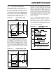
PWM outputs. Figure 12-16 shows the four dead-time
units that each have their own dead-time value.
Dead-time generation can be provided when any of the
PWM I/O pin pairs are operating in any output mode.
Many power-converter circuits require dead time
because the power transistors cannot switch instanta-
neously. To prevent current “shoot-through” some
amount of time must be provided between the turn-off
event of one PWM output in a complementary pair and
the turn-on event of the other transistor.
The PWM module can also provide negative dead time.
Negative dead time is the forced overlap of the PWMH
and PWML signals. There are certain converter tech-
niques that require a limited amount of
current “shoot-through”.
The dead-time feature can be disabled for each PWM
generator. The dead-time functionality is controlled by
the DTC<1:0> bits in the PWMCON register.
FIGURE 12-15: DEAD-TIME INSERTION
FOR COMPLEMENTARY
PWM
FIGURE 12-16: DEAD-TIME CONTROL
UNITS BLOCK DIAGRAM
12.14.1 DEAD-TIME GENERATORS
Each complementary output pair for the PWM module
has 12-bit down counters to produce the dead-time
insertion. Each dead-time unit has a rising and falling
edge detector connected to the duty cycle comparison
output.
Depending on whether the edge is rising or falling, one
of the transitions on the complementary outputs is
delayed until the associated timer counts down to
zero. A timing diagram indicating the dead-time inser-
tion for one pair of PWM outputs is shown in
Figure 12-15.
12.14.2 ALTERNATE DEAD-TIME SOURCE
The alternate dead time refers to the dead time speci-
fied by the ALTDTR register that is applied to the com-
plementary PWM output. Figure 12-17 shows a dual
dead-time insertion using the ALTDTR register.
Note: If zero dead time is required, the dead time
feature must be explicitly disabled in the
DTC<1:0> bit in the PWMCON register
PWM1H
PWM1L
t
da
t
da
PWM
Generator #1
Output
DTR1
Dead-Time Unit
#1
PWM1 in
PWM1H
PWM1L
ALTDR1
DTR2
Dead-Time Unit
#2
PWM2 in
PWM2H
PWM2L
ALTDTR2
DTR3
Dead-Time Unit
#3
PWM3 in
PWM3H
PWM3L
ALTDTR3
DTR4
Dead-Time Unit
#4
PWM4 in
PWM4H
PWM4L
ALTDTR4