
Datasheet


© 2006 Microchip Technology Inc. Preliminary DS70178C-page 125
dsPIC30F1010/202X
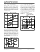
FIGURE 12-13: TMRx BLOCK DIAGRAM
Normally, the Primary Time Base (PTMR) provides
synchronization control to the individual timer/counters
so they count in lock-step unison.
If the PWM phase-shift feature is used, then the PTMR
provides the synchronization signal to each individual
timer/counter that causes them to reinitialize with their
individual phase-shift values.
If a PWM generator is operating in Independent Time
Base mode, the individual timer/counters count
upward until their count values match the value stored
in their phase registers, then they reset and the cycle
repeats.
The primary time base and the individual time bases
are implemented as 13-bit counters. The timers/
counters are clocked at 120 MHz @ 30 MIPS, which
provides a frequency resolution of 8.4 nsec.
All of the timer/counters are enabled/disabled by set-
ting/clearing the PTEN bit in the PTCON SFR. The
timers are cleared when the PTEN bit is cleared in
software.
The PTPER register sets the counting period for
PTMR. The user must write a 13-bit value to
PTPER<15:3>. When the value in PTMR<15:3>
matches the value in PTPER<15:3>, the primary time
base is reset to ‘0’, and the individual time base
counters are reinitialized to their phase values (except
if in Independent Time Base mode).
12.8 PWM Period
PTPER holds the 13-bit value that specifies the count-
ing period for the primary PWM time base. The timer
period can be updated at any time by the user. The
PWM period can be determined from the following
formula:
Period Duration = (PTPER + 1)/120 MHz @ 30 MIPS
12.9 PWM Frequency and Duty Cycle
Resolution
The PWM Duty cycle resolution is 1.05 nsec per LSB
@ 30 MIPS. The PWM period resolution is 8.4 nsec @
30 MIPS. Table 12-1 shows the duty cycle resolution
versus PWM frequencies for 30 MIPS execution speed.
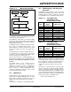
TABLE 12-1: AVAILABLE PWM
FREQUENCIES AND
RESOLUTIONS @ 30 MIPS
TABLE 12-2: AVAILABLE PWM
FREQUENCIES AND
RESOLUTIONS @ 20 MIPS
Notice the reduction in available resolution for a given
PWM frequency is due to the reduced clock rate and
the fact that the LSB of duty cycle resolution is derived
from a fixed-delay element. At operating frequencies
below 30 MIPS, the contribution of the fixed-delay
element to the output resolution becomes less than
1 LSB.
For frequency resonant mode power conversion appli-
cations, it is desirable to know the available PWM fre-
quency resolution. The available frequency resolution
varies with the PWM frequency. The PWM time base
clocks at 120 MHz @ 30 MIPS. The following equation
provides the frequency resolution versus PWM period:
Frequency Resolution = 120 MHz/(Period)
where Period = PTPER<15:3>
TMRx
PTPER
Comparator
Clk
>
Reset
13
13
MUX
PHASEx
ITBx
0
1
15 3 15
3
15
3
MIPS
PWM Duty
Cycle
Resolution
PWM Frequency
30 16 bits 14.6 KHz
30 15 bits 29.3 KHz
30 14 bits 58.6 KHz
30 13 bits 117.2 KHz
30 12 bits 234.4 KHz
30 11 bits 468.9 KHz
30 10 bits 937.9 KHz
30 9 bits 1.87 MHz
30 8 bits 3.75 MHz
MIPS
PWM Duty
Cycle
Resolution
PWM Frequency
20 14 bits 39 KHz
20 12 bits 156 KHz
20 10 bits 624 KHz
20 8 bits 2.5 MHz