
Datasheet


© 2006 Microchip Technology Inc. Preliminary DS70178C-page 121
dsPIC30F1010/202X
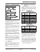
12.4 Module Functionality
The PS PWM module is a very high-speed design that
provides capabilities not found in other PWM genera-
tors. The module supports these PWM modes:
• Standard Edge-Aligned PWM mode
• Complementary PWM mode
• Push-Pull PWM mode
• Multi-Phase PWM mode
• Variable Phase PWM mode
• Current-Limit PWM mode
• Constant Off-time PWM mode
• Current Reset PWM mode
• Independent Time Base PWM mode
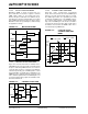
12.4.1 STANDARD EDGE-ALIGNED PWM
MODE
Standard Edge-Aligned mode (Figure 12-3) is the basic
PWM mode used by many power converter topologies
such as “Buck”, “Boost” and “Forward”. To create the
edge-aligned PWM, a timer/counter circuit counts
upward from zero to a specified maximum value for the
Period. Another register contains the value for Duty
Cycle, which is constantly compared to the timer
(Period) value. While the timer/counter value is less
than or equal to the duty cycle value, the PWM output
signal is asserted. When the timer value exceeds the
duty cycle value, the PWM signal is deasserted. When
the timer is greater than the period value, the timer is
reset, and the process repeats.
FIGURE 12-3: EDGE-ALIGNED PWM
12.4.2 COMPLEMENTARY PWM MODE
Complementary PWM is generated in a manner similar
to standard Edge-Aligned PWM. Complementary mode
provides a second PWM output signal on the PWML
pin that is the complement of the primary PWM signal
(PWMH). Complementary mode PWM is shown in
Figure 12-4.
FIGURE 12-4: COMPLEMENTARY PWM
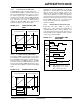
12.4.3 PUSH-PULL PWM MODE
The Push-Pull mode shown in Figure 12-5 is a version
of the standard Edge-Aligned PWM mode where the
active PWM signal is alternately outputted on one of
two PWM pins. There is no complementary PWM out-
put available. This mode is useful in transformer-based
power converters. Transformer-based circuits must
avoid any direct currents that will cause their cores to
saturate. The Push-Pull mode ensures that the duty
cycle of the two phases is identical, thus yielding a net
DC bias of zero.
FIGURE 12-5: PUSH-PULL PWM
Period
Duty Cycle
0
Period
Timer
Value
Timer Resets
PWMH
Value
Duty Cycle Match
Period
Duty Cycle
0
Period
Timer
Value
Timer Resets
PWMH
Value
PWML
(Period)-(Duty Cycle)
Duty Cycle Match
Period
Duty Cycle
0
Period
Timer
Value
Timer Resets
PWMH
Value
PWML
Duty Cycle
Duty Cycle Match