
Datasheet


dsPIC30F1010/202X
DS70178C-page 112 Preliminary © 2006 Microchip Technology Inc.
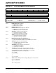
REGISTER 12-4: MDC: PWM MASTER DUTY CYCLE REGISTER
R/W-0 R/W-0 R/W-0 R/W-0 R/W-0 R/W-0 R/W-0 R/W-0
MDC<15:8>
bit 15 bit 8
R/W-0 R/W-0 R/W-0 R/W-0 R/W-0 R/W-0 R/W-0 R/W-0
MDC<7:0>
bit 7 bit 0
Legend:
R = Readable bit W = Writable bit U = Unimplemented bit, read as ‘0’
-n = Value at POR ‘1’ = Bit is set ‘0’ = Bit is cleared x = Bit is unknown
bit 15-0 Master PWM Duty Cycle Value bits
(1)
Note 1: The minimum value for this register is 0x0008 and the maximum value is 0xFFEF.
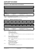
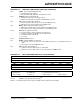
REGISTER 12-5: PWMCONx: PWM CONTROL REGISTER
HS/HC-0 HS/HC-0 HS/HC-0 R/W-0 R/W-0 R/W-0 R/W-0 R/W-0
FLTSTAT CLSTAT TRGSTAT FLTIEN CLIEN TRGIEN ITB MDCS
bit 15 bit 8
R/W-0 R/W-0 U-0 U-0 U-0 U-0 R/W-0 R/W-0
DTC<1:0>
— — — — XPRES IUE
bit 7 bit 0
Legend:
R = Readable bit W = Writable bit U = Unimplemented bit, read as ‘0’
-n = Value at POR ‘1’ = Bit is set ‘0’ = Bit is cleared x = Bit is unknown
bit 15 FLTSTAT: Fault Interrupt Status
1 = Fault Interrupt is pending
0 = No Fault Interrupt is pending
This bit is cleared by setting FLTIEN = 0.
Note: Software must clear the interrupt status here, and the corresponding IFS bit in Interrupt
Controller.
bit 14 CLSTAT: Current-Limit Interrupt Status bit
1 = Current-limit interrupt is pending
0 = No current-limit interrupt is pending
This bit is cleared by setting CLIEN = 0.
Note: Software must clear the interrupt status here, and the corresponding IFS bit in Interrupt
Controller.
bit 13 TRGSTAT: Trigger Interrupt Status bit
1 = Trigger interrupt is pending
0 = No trigger interrupt is pending
This bit is cleared by setting TRGIEN = 0.
bit 12 FLTIEN: Fault Interrupt Enable bit
1 = Fault interrupt enabled
0 = Fault interrupt disabled and FLTSTAT bit is cleared