dsPIC30F1010/202X Data Sheet 28/44-Pin High-Performance Switch Mode Power Supply Digital Signal Controllers © 2006 Microchip Technology Inc.
Note the following details of the code protection feature on Microchip devices: • Microchip products meet the specification contained in their particular Microchip Data Sheet. • Microchip believes that its family of products is one of the most secure families of its kind on the market today, when used in the intended manner and under normal conditions. • There are dishonest and possibly illegal methods used to breach the code protection feature.
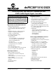
dsPIC30F1010/202X 28/44-Pin dsPIC30F1010/202X Enhanced Flash SMPS 16-Bit Digital Signal Controller Note: This data sheet summarizes features of this group of dsPIC30F devices and is not intended to be a complete reference source. For more information on the CPU, peripherals, register descriptions and general device functionality, refer to the “dsPIC30F Family Reference Manual” (DS70046).
dsPIC30F1010/202X Analog Features: Special Microcontroller Features: ADC • Enhanced Flash program memory: - 10,000 erase/write cycle (min.
dsPIC30F1010/202X Pin Diagrams 1 2 3 4 5 6 7 8 9 10 11 12 13 14 MCLR AN0/CMP1A/CN2/RB0 AN1/CMP1B/CN3/RB1 AN2/CMP1C/CMP2A/CN4/RB2 AN3/CMP1D/CMP2B/CN5/RB3 AN4/CMP2C/CN6/RB4 AN5/CMP2D/CN7/RB5 VSS OSC1/CLKI/RB6 OSC2/CLKO/RB7 PGD1/EMUD1/T2CK/U1ATX/CN1/RE7 PGC1/EMUC1/EXTREF/T1CK/U1ARX/CN0/RE6 VDD PGD2/EMUD2/SCK1/SFLT3/INT2/RF6 dsPIC30F1010 28-Pin SDIP and SOIC 28 27 26 25 24 23 22 21 20 19 18 17 16 15 AVDD AVSS PWM1L/RE0 PWM1H/RE1 PWM2L/RE2 PWM2H/RE3 RE4 RE5 VDD VSS PGC/EMUC/SDI1/SDA/U1RX/RF7 PGD/EMUD/SDO1/S
dsPIC30F1010/202X Pin Diagrams MCLR AN0/CMP1A/CN2/RB0 AN1/CMP1B/CN3/RB1 AN2/CMP1C/CMP2A/CN4/RB2 AN3/CMP1D/CMP2B/CN5/RB3 AN4/CMP2C/CMP3A/CN6/RB4 AN5/CMP2D/CMP3B/CN7/RB5 VSS AN6/CMP3C/CMP4A/OSC1/CLKI/RB6 AN7/CMP3D/CMP4B/OSC2/CLKO/RB7 PGD1/EMUD1/PWM4H/T2CK/U1ATX/CN1/RE7 PGC1/EMUC1/EXTREF/PWM4L/T1CK/U1ARX/CN0/RE6 VDD PGD2/EMUD2/SCK1/SFLT3/OC2/INT2/RF6 28 27 26 25 24 23 22 21 20 19 18 17 16 15 AVDD AVSS PWM1L/RE0 PWM1H/RE1 PWM2L/RE2 PWM2H/RE3 PWM3L/RE4 PWM3H/RE5 VDD VSS PGC/EMUC/SDI1/SDA/U1RX/RF7 PGD/EMUD/SDO
dsPIC30F1010/202X Pin Diagrams PGD/EMUD/SDO1/RF8 SFLT2/INT0/OCFLTA/RA9 PGC2/EMUC2/OC1/IC1/INT1/RD0 PGD2/EMUD2/SCK1/INT2/RF6 VDD VSS OC2/RD1 SFLT1/RA8 AN9/EXTREF/CMP4D/RB9 PGC1/EMUC1/PWM4L/T1CK/U1ARX/CN0/RE6 PGD1/EMUD1/PWM4H/T2CK/U1ATX/CN1/RE7 44-PIN QFN 44 43 42 41 40 39 38 37 36 35 34 PGC/EMUC/SDI1/RF7 SYNCO/SS1/RF15 SFLT3/RA10 SFLT4/RA11 SDA/RG3 VSS VDD PWM3H/RE5 PWM3L/RE4 PWM2H/RE3 PWM2L/RE2 1 2 3 4 5 6 7 8 9 10 11 dsPIC30F2023 33 32 31 30 29 28 27 26 25 24 23 AN7/CMP3D/CMP4B/OSC2/CLKO/RB7 AN6/CMP3
dsPIC30F1010/202X PGD/EMUD/SDO1/RF8 SFLT2/INT0/OCFLTA/RA9 PGC2/EMUC2/OC1/IC1/INT1/RD0 PGD2/EMUD2/SCK1/INT2/RF6 VDD VSS OC2/RD1 SFLT1/RA8 AN9/EXTREF/CMP4D/RB9 PGC1/EMUC1/PWM4L/T1CK/U1ARX/CN0/RE6 PGD1/EMUD1/PWM4H/T2CK/U1ATX/CN1/RE7 Pin Diagrams 44 43 42 41 40 39 38 37 36 35 34 44-Pin TQFP 1 2 3 4 5 6 7 8 9 10 11 dsPIC30F2023 33 32 31 30 29 28 27 26 25 24 23 AN7/CMP3D/CMP4B/OSC2/CLKO/RB7 AN6/CMP3C/CMP4A/OSC1/CLKI/RB6 AN8/CMP4C/RB8 VSS VDD AN10/IFLT4/RB10 AN11/IFLT2/RB11 AN5/CMP2D/CMP3B/CN7/RB5 AN4/CMP2C
dsPIC30F1010/202X Table of Contents 1.0 2.0 3.0 4.0 5.0 6.0 7.0 8.0 9.0 10.0 11.0 12.0 13.0 14.0 15.0 16.0 17.0 18.0 19.0 20.0 21.0 22.0 Device Overview .......................................................................................................................................................................... 9 CPU Architecture Overview........................................................................................................................................................
dsPIC30F1010/202X TO OUR VALUED CUSTOMERS It is our intention to provide our valued customers with the best documentation possible to ensure successful use of your Microchip products. To this end, we will continue to improve our publications to better suit your needs. Our publications will be refined and enhanced as new volumes and updates are introduced.
dsPIC30F1010/202X 1.0 DEVICE OVERVIEW Note: This data sheet summarizes features of this group of dsPIC30F devices and is not intended to be a complete reference source. For more information on the CPU, peripherals, register descriptions and general device functionality, refer to the “dsPIC30F Family Reference Manual” (DS70046). For more information on the device instruction set and programming, refer to the “dsPIC30F/ 33F Programmer’s Reference Manual” (DS70157). © 2006 Microchip Technology Inc.
dsPIC30F1010/202X FIGURE 1-1: dsPIC30F1010 BLOCK DIAGRAM Y Data Bus X Data Bus 16 Interrupt Controller PSV & Table Data Access 24 Control Block 8 16 16 Data Latch Y Data RAM (256 bytes) Address Latch 16 24 24 16 SFLT2/INT0/OCFLTA/RA9 PORTA 16 X RAGU X WAGU Y AGU PCU PCH PCL Program Counter Loop Stack Control Control Logic Logic Data Latch X Data RAM (256 bytes) Address Latch 16 16 Address Latch 16 AN0/CMP1A/CN2/RB0 AN1/CMP1B/CN3/RB1 AN2/CMP1C/CMP2A/CN4/RB2 AN3/CMP1D/CMP2B/CN5/RB3 AN4/CMP
dsPIC30F1010/202X Table 1-1 provides a brief description of device I/O pinouts for the dsPIC30F1010 and the functions that may be multiplexed to a port pin. Multiple functions may exist on one port pin. When multiplexing occurs, the peripheral module’s functional requirements may force an override of the data direction of the port pin. TABLE 1-1: PINOUT I/O DESCRIPTIONS FOR dsPIC30F1010 Pin Type Buffer Type AN0-AN5 I Analog Pin Name Description Analog input channels.
dsPIC30F1010/202X TABLE 1-1: PINOUT I/O DESCRIPTIONS FOR dsPIC30F1010 (CONTINUED) Pin Type Buffer Type RE0-RE7 I/O ST PORTE is a bidirectional I/O port. RF6, RF7, RF8 I/O ST PORTF is a bidirectional I/O port. SCK1 SDI1 SDO1 I/O I O ST ST — Synchronous serial clock input/output for SPI #1. SPI #1 Data In. SPI #1 Data Out. SCL SDA I/O I/O ST ST Synchronous serial clock input/output for I2C™. Synchronous serial data input/output for I2C. T1CK T2CK I I ST ST Timer1 external clock input.
dsPIC30F1010/202X FIGURE 1-2: dsPIC30F2020 BLOCK DIAGRAM Y Data Bus X Data Bus 16 Interrupt Controller PSV & Table Data Access 24 Control Block 8 16 16 Data Latch Y Data RAM (256 bytes) Address Latch 16 24 24 16 SFLT2/INT0/OCFLTA/RA9 PORTA 16 X RAGU X WAGU Y AGU PCU PCH PCL Program Counter Loop Stack Control Control Logic Logic Data Latch X Data RAM (256 bytes) Address Latch 16 16 Address Latch 16 AN0/CMP1A/CN2/RB0 AN1/CMP1B/CN3/RB1 AN2/CMP1C/CMP2A/CN4/RB2 AN3/CMP1D/CMP2B/CN5/RB3 AN4/CMP
dsPIC30F1010/202X Table 1-2 provides a brief description of device I/O pinouts for the dsPIC30F2020 and the functions that may be multiplexed to a port pin. Multiple functions may exist on one port pin. When multiplexing occurs, the peripheral module’s functional requirements may force an override of the data direction of the port pin. TABLE 1-2: PINOUT I/O DESCRIPTIONS FOR dsPIC30F2020 Pin Type Buffer Type AN0-AN7 I Analog AVDD P P Positive supply for analog module.
dsPIC30F1010/202X TABLE 1-2: PINOUT I/O DESCRIPTIONS FOR dsPIC30F2020 (CONTINUED) Pin Type Buffer Type RB0-RB7 I/O ST RA9 I/O ST PORTA is a bidirectional I/O port. RD0 I/O ST PORTD is a bidirectional I/O port. RE0-RE7 I/O ST PORTE is a bidirectional I/O port. RF6, RF7, RF8 I/O ST PORTF is a bidirectional I/O port. SCK1 SDI1 SDO1 I/O I O ST ST — Synchronous serial clock input/output for SPI #1. SPI #1 Data In. SPI #1 Data Out.
dsPIC30F1010/202X FIGURE 1-3: dsPIC30F2023 BLOCK DIAGRAM Y Data Bus X Data Bus 16 Interrupt Controller PSV & Table Data Access 24 Control Block 8 16 16 Data Latch Y Data RAM (256 bytes) Address Latch 16 24 16 SFLT1/RA8 SFLT2/INT0/OCFLTA/RA9 SFLT3/RA10 SFLT4/RA11 PORTA X RAGU X WAGU Y AGU PCU PCH PCL Program Counter Loop Stack Control Control Logic Logic 16 Data Latch X Data RAM (256 bytes) Address Latch 16 16 24 Address Latch 16 AN0/CMP1A/CN2/RB0 AN1/CMP1B/CN3/RB1 AN2/CMP1C/CMP2A/CN4/RB2
dsPIC30F1010/202X Table 1-3 provides a brief description of device I/O pinouts for the dsPIC30F2023 and the functions that may be multiplexed to a port pin. Multiple functions may exist on one port pin. When multiplexing occurs, the peripheral module’s functional requirements may force an override of the data direction of the port pin. TABLE 1-3: PINOUT I/O DESCRIPTIONS FOR dsPIC30F2023 Pin Type Buffer Type AN0-AN11 I Analog AVDD P P Positive supply for analog module.
dsPIC30F1010/202X TABLE 1-3: PINOUT I/O DESCRIPTIONS FOR dsPIC30F2023 (CONTINUED) Pin Type Buffer Type PGD PGC PGD1 PGC1 PGD2 PGC2 I/O I I/O I I/O I ST ST ST ST ST ST In-Circuit Serial Programming™ data input/output pin. In-Circuit Serial Programming clock input pin. In-Circuit Serial Programming data input/output pin 1. In-Circuit Serial Programming clock input pin 1. In-Circuit Serial Programming data input/output pin 2. In-Circuit Serial Programming clock input pin 2.
dsPIC30F1010/202X 2.0 CPU ARCHITECTURE OVERVIEW Note: This data sheet summarizes features of this group of dsPIC30F devices and is not intended to be a complete reference source. For more information on the CPU, peripherals, register descriptions and general device functionality, refer to the “dsPIC30F Family Reference Manual” (DS70046). For more information on the device instruction set and programming, refer to the “dsPIC30F/ 33F Programmer’s Reference Manual” (DS70157). 2.
dsPIC30F1010/202X 2.2 2.2.1 Programmer’s Model The programmer’s model is shown in Figure 2-1 and consists of 16x16-bit working registers (W0 through W15), 2x40-bit accumulators (ACCA and ACCB), STATUS register (SR), Data Table Page register (TBLPAG), Program Space Visibility Page register (PSVPAG), DO and REPEAT registers (DOSTART, DOEND, DCOUNT and RCOUNT), and Program Counter (PC). The working registers can act as data, address or offset registers. All registers are memory mapped.
dsPIC30F1010/202X FIGURE 2-1: PROGRAMMER’S MODEL D15 D0 W0/WREG PUSH.
dsPIC30F1010/202X 2.3 Divide Support The dsPIC DSC devices feature a 16/16-bit signed fractional divide operation, as well as 32/16-bit and 16/ 16-bit signed and unsigned integer divide operations, in the form of single instruction iterative divides. The following instructions and data sizes are supported: 1. 2. 3. 4. 5. DIVF – 16/16 signed fractional divide DIV.sd – 32/16 signed divide DIV.ud – 32/16 unsigned divide DIV.sw – 16/16 signed divide DIV.
dsPIC30F1010/202X 2.4 DSP Engine The DSP engine consists of a high speed 17-bit x 17-bit multiplier, a barrel shifter, and a 40-bit adder/subtracter (with two target accumulators, round and saturation logic). The DSP engine also has the capability to perform inherent accumulator-to-accumulator operations, which require no additional data. These instructions are ADD, SUB and NEG.
dsPIC30F1010/202X FIGURE 2-2: DSP ENGINE BLOCK DIAGRAM 40 S a 40 Round t 16 u Logic r a t e 40-bit Accumulator A 40-bit Accumulator B Carry/Borrow Out Carry/Borrow In Saturate Adder Negate 40 40 40 16 X Data Bus Barrel Shifter 40 Y Data Bus Sign-Extend 32 16 Zero Backfill 32 33 17-bit Multiplier/Scaler 16 16 To/From W Array DS70178C-page 24 Preliminary © 2006 Microchip Technology Inc.
dsPIC30F1010/202X 2.4.1 MULTIPLIER 2.4.2.1 The 17x17-bit multiplier is capable of signed or unsigned operation and can multiplex its output using a scaler to support either 1.31 fractional (Q31) or 32-bit integer results. Unsigned operands are zero-extended into the 17th bit of the multiplier input value. Signed operands are sign-extended into the 17th bit of the multiplier input value. The output of the 17x17-bit multiplier/ scaler is a 33-bit value, which is sign-extended to 40 bits.
dsPIC30F1010/202X The SA and SB bits are modified each time data passes through the adder/subtracter, but can only be cleared by the user. When set, they indicate that the accumulator has overflowed its maximum range (bit 31 for 32-bit saturation, or bit 39 for 40-bit saturation) and will be saturated (if saturation is enabled). When saturation is not enabled, SA and SB default to bit 39 overflow and thus indicate that a catastrophic overflow has occurred.
dsPIC30F1010/202X 2.4.2.4 Data Space Write Saturation 2.4.3 In addition to adder/subtracter saturation, writes to data space may also be saturated, but without affecting the contents of the source accumulator. The data space write saturation logic block accepts a 16-bit, 1.15 fractional value from the round logic block as its input, together with overflow status from the original source (accumulator) and the 16-bit round adder. These are combined and used to select the appropriate 1.
dsPIC30F1010/202X NOTES: DS70178C-page 28 Preliminary © 2006 Microchip Technology Inc.
dsPIC30F1010/202X 3.0 MEMORY ORGANIZATION FIGURE 3-1: Note: This data sheet summarizes features of this group of dsPIC30F devices and is not intended to be a complete reference source. For more information on the CPU, peripherals, register descriptions and general device functionality, refer to the “dsPIC30F Family Reference Manual” (DS70046). For more information on the device instruction set and programming, refer to the “dsPIC30F/ 33F Programmer’s Reference Manual” (DS70157).
dsPIC30F1010/202X TABLE 3-1: PROGRAM SPACE ADDRESS CONSTRUCTION Instruction Access TBLRD/TBLWT TBLRD/TBLWT Program Space Visibility FIGURE 3-2: Program Space Address <23> <22:16> <15> <14:1> 0 PC<22:1> TBLPAG<7:0> Data EA <15:0> Access Space Access Type User User (TBLPAG<7> = 0) Configuration (TBLPAG<7> = 1) User TBLPAG<7:0> 0 <0> 0 Data EA <15:0> PSVPAG<7:0> Data EA <14:0> DATA ACCESS FROM PROGRAM SPACE ADDRESS GENERATION 23 bits Using Program Counter Program Counter 0 Select Using Program
dsPIC30F1010/202X 3.1.1 DATA ACCESS FROM PROGRAM MEMORY USING TABLE INSTRUCTIONS A set of Table Instructions is provided to move byte or word sized data to and from program space. 1. This architecture fetches 24-bit wide program memory. Consequently, instructions are always aligned. However, as the architecture is modified Harvard, data can also be present in program space.
dsPIC30F1010/202X FIGURE 3-4: PROGRAM DATA TABLE ACCESS (MOST SIGNIFICANT BYTE) TBLRDH.W PC Address 0x000000 0x000002 0x000004 0x000006 23 16 8 0 00000000 00000000 00000000 00000000 TBLRDH.B (Wn<0> = 0) Program Memory ‘Phantom’ Byte (Read as ‘0’) 3.1.2 TBLRDH.B (Wn<0> = 1) DATA ACCESS FROM PROGRAM MEMORY USING PROGRAM SPACE VISIBILITY The upper 32 Kbytes of data space may optionally be mapped into any 16K word program space page.
dsPIC30F1010/202X FIGURE 3-5: DATA SPACE WINDOW INTO PROGRAM SPACE OPERATION Data Space Program Space 0x100100 0x0000 PSVPAG(1) 0x00 8 15 EA<15> = 0 Data Space EA 16 15 EA<15> = 1 0x8000 Address 15 Concatenation 23 23 15 0 0x001200 Upper half of Data Space is mapped into Program Space 0x001FFE 0xFFFF BSET MOV MOV MOV CORCON,#2 #0x00, W0 W0, PSVPAG 0x9200, W0 ; PSV bit set ; Set PSVPAG register ; Access program memory location ; using a data space access Data Read Note: PSVPAG is an 8-bit
dsPIC30F1010/202X FIGURE 3-6: DATA SPACE MEMORY MAP MSB Address MSB SFR Space (Note) 0x0001 LSB Address 16 bits LSB 0x0000 SFR Space 0x07FE 0x0800 0x07FF 0x0801 2560 bytes Near Data Space X Data RAM (X) 256 bytes 512 bytes SRAM Space 0x08FF 0x0901 0x08FE 0x0900 Y Data RAM (Y) 256 bytes 0x09FF 0x09FE 0x0A00 (See Note) 0x8001 0x8000 X Data Unimplemented (X) Optionally Mapped into Program Memory 0xFFFE 0xFFFF Note: Unimplemented SFR or SRAM locations read as ‘0’.
dsPIC30F1010/202X DATA SPACE FOR MCU AND DSP (MAC CLASS) INSTRUCTIONS SFR SPACE SFR SPACE X SPACE FIGURE 3-7: Y SPACE UNUSED X SPACE (Y SPACE) X SPACE UNUSED UNUSED Non-MAC Class Ops (Read/Write) MAC Class Ops (Write) Indirect EA using any W © 2006 Microchip Technology Inc.
dsPIC30F1010/202X 3.2.2 DATA SPACES 3.2.3 The X data space is used by all instructions and supports all Addressing modes. There are separate read and write data buses. The X read data bus is the return data path for all instructions that view data space as combined X and Y address space. It is also the X address space data path for the dual operand read instructions (MAC class). The X write data bus is the only write path to data space for all instructions.
dsPIC30F1010/202X A Sign-Extend (SE) instruction is provided to allow users to translate 8-bit signed data to 16-bit signed values. Alternatively, for 16-bit unsigned data, users can clear the MSB of any W register by executing a Zero-Extend (ZE) instruction on the appropriate address. Although most instructions are capable of operating on word or byte data sizes, it should be noted that some instructions, including the DSP instructions, operate only on words. 3.2.
SFR Name Addr.
© 2006 Microchip Technology Inc. TABLE 3-3: SFR Name CORE REGISTER MAP (CONTINUED) Addr.
dsPIC30F1010/202X NOTES: DS70178C-page 40 Preliminary © 2006 Microchip Technology Inc.
dsPIC30F1010/202X 4.0 ADDRESS GENERATOR UNITS Note: This data sheet summarizes features of this group of dsPIC30F devices and is not intended to be a complete reference source. For more information on the CPU, peripherals, register descriptions and general device functionality, refer to the “dsPIC30F Family Reference Manual” (DS70046). For more information on the device instruction set and programming, refer to the “dsPIC30F/ 33F Programmer’s Reference Manual” (DS70157).
dsPIC30F1010/202X 4.1.2 MCU INSTRUCTIONS 4.1.4 The three-operand MCU instructions are of the form: Operand 3 = Operand 1 Operand 2 where Operand 1 is always a working register (i.e., the Addressing mode can only be register direct), which is referred to as Wb. Operand 2 can be a W register, fetched from data memory, or a 5-bit literal. The result location can be either a W register or an address location.
dsPIC30F1010/202X 4.2 4.2.1 Modulo Addressing Modulo addressing is a method of providing an automated means to support circular data buffers using hardware. The objective is to remove the need for software to perform data address boundary checks when executing tightly looped code, as is typical in many DSP algorithms. Modulo addressing can operate in either data or program space (since the data pointer mechanism is essentially the same for both).
dsPIC30F1010/202X FIGURE 4-1: MODULO ADDRESSING OPERATION EXAMPLE Byte Address MOV MOV MOV MOV MOV MOV MOV MOV DO MOV AGAIN: 0x1100 #0x1100,W0 W0, XMODSRT #0x1163,W0 W0,MODEND #0x8001,W0 W0,MODCON #0x0000,W0 #0x1110,W1 AGAIN,#0x31 W0, [W1++] INC W0,W0 ;set modulo start address ;set modulo end address ;enable W1, X AGU for modulo ;W0 holds buffer fill value ;point W1 to buffer ;fill the 50 buffer locations ;fill the next location ;increment the fill value 0x1163 Start Addr = 0x1100 End Addr = 0x1163
dsPIC30F1010/202X 4.2.3 MODULO ADDRESSING APPLICABILITY Modulo addressing can be applied to the Effective Address (EA) calculation associated with any W register. It is important to realize that the address boundaries check for addresses less than or greater than the upper (for incrementing buffers) and lower (for decrementing buffers) boundary addresses (not just equal to). Address changes may, therefore, jump beyond boundaries and still be adjusted correctly. Note: 4.
dsPIC30F1010/202X TABLE 4-2: BIT-REVERSED ADDRESS SEQUENCE (16-ENTRY) Normal Address A3 A2 A1 A0 Bit-Reversed Address Decimal A3 A2 A1 A0 Decimal 0 0 0 0 0 0 0 0 0 0 0 0 0 1 1 1 0 0 0 8 0 0 1 0 2 0 1 0 0 4 0 0 1 1 3 1 1 0 0 12 0 1 0 0 4 0 0 1 0 2 0 1 0 1 5 1 0 1 0 10 0 1 1 0 6 0 1 1 0 6 0 1 1 1 7 1 1 1 0 14 1 0 0 0 8 0 0 0 1 1 1 0 0 1 9 1 0 0 1 9 1 0 1 0 10 0 1 0 1 5 1 0 1 1 11 1 1
dsPIC30F1010/202X 5.0 INTERRUPTS Note: This data sheet summarizes features of this group of dsPIC30F devices and is not intended to be a complete reference source. For more information on the CPU, peripherals, register descriptions and general device functionality, refer to the “dsPIC30F Family Reference Manual” (DS70046). For more information on the device instruction set and programming, refer to the “dsPIC30F/ 33F Programmer’s Reference Manual” (DS70157).
dsPIC30F1010/202X 5.1 TABLE 5-1: Interrupt Priority The user-assignable Interrupt Priority (IP<2:0>) bits for each individual interrupt source are located in the Least Significant 3 bits of each nibble, within the IPCx register(s). Bit 3 of each nibble is not used and is read as a ‘0’. These bits define the priority level assigned to a particular interrupt by the user. Note: The user selectable priority levels start at 0, as the lowest priority, and level 7, as the highest priority.
dsPIC30F1010/202X 5.2 Reset Sequence 5.3 A Reset is not a true exception, because the interrupt controller is not involved in the Reset process. The processor initializes its registers in response to a Reset, which forces the PC to zero. The processor then begins program execution at location 0x000000. A GOTO instruction is stored in the first program memory location, immediately followed by the address target for the GOTO instruction.
dsPIC30F1010/202X Address Error Trap: 5.3.2 This trap is initiated when any of the following circumstances occurs: It is possible that multiple traps can become active within the same cycle (e.g., a misaligned word stack write to an overflowed address). In such a case, the fixed priority shown in Figure 5-1 is implemented, which may require the user to check if other traps are pending, in order to completely correct the fault. 1. 2. 3. 4. A misaligned data word access is attempted.
dsPIC30F1010/202X 5.4 Interrupt Sequence 5.5 All interrupt event flags are sampled in the beginning of each instruction cycle by the IFSx registers. A pending interrupt request (IRQ) is indicated by the flag bit being equal to a ‘1’ in an IFSx register. The IRQ will cause an interrupt to occur if the corresponding bit in the interrupt enable (IECx) register is set. For the remainder of the instruction cycle, the priorities of all pending interrupt requests are evaluated.
dsPIC30F1010/202X REGISTER 5-1: INTCON1: INTERRUPT CONTROL REGISTER 1 R/W-0 R/W-0 R/W-0 R/W-0 R/W-0 R/W-0 R/W-0 R/W-0 NSTDIS OVAERR OVBERR COVAERR COVBERR OVATE OVBTE COVTE bit 15 bit 8 R/W-0 R/W-0 U-0 R/W-0 R/W-0 R/W-0 R/W-0 U-0 SFTACERR DIV0ERR — MATHERR ADDRERR STKERR OSCFAIL — bit 7 bit 0 Legend: R = Readable bit W = Writable bit U = Unimplemented bit, read as ‘0’ -n = Value at POR ‘1’ = Bit is set ‘0’ = Bit is cleared bit 15 NSTDIS: Interrupt Nesting Disable
dsPIC30F1010/202X REGISTER 5-1: INTCON1: INTERRUPT CONTROL REGISTER 1 (CONTINUED) bit 2 STKERR: Stack Error Trap Status bit 1 = Stack error trap has occurred 0 = Stack error trap has not occurred bit 1 OSCFAIL: Oscillator Failure Trap Status bit 1 = Oscillator failure trap has occurred 0 = Oscillator failure trap has not occurred bit 0 Unimplemented: Read as ‘0’ © 2006 Microchip Technology Inc.
dsPIC30F1010/202X REGISTER 5-2: INTCON2: INTERRUPT CONTROL REGISTER 2 R/W-0 R-0 U-0 U-0 U-0 U-0 U-0 U-0 ALTIVT DISI — — — — — — bit 15 bit 8 U-0 U-0 U-0 U-0 U-0 R/W-0 R/W-0 R/W-0 — — — — — INT2EP INT1EP INT0EP bit 7 bit 0 Legend: R = Readable bit W = Writable bit U = Unimplemented bit, read as ‘0’ -n = Value at POR ‘1’ = Bit is set ‘0’ = Bit is cleared bit 15 ALTIVT: Enable Alternate Interrupt Vector Table bit 1 = Use alternate vector table 0 = Use standard (defa
dsPIC30F1010/202X REGISTER 5-3: IFS0: INTERRUPT FLAG STATUS REGISTER 0 U-0 R/W-0 R/W-0 R/W-0 R/W-0 R/W-0 R/W-0 R/W-0 — MI2CIF SI2CIF NVMIF ADIF U1TXIF U1RXIF SPI1IF bit 15 bit 8 R/W-0 R/W-0 R/W-0 U-0 R/W-0 R/W-0 R/W-0 R/W-0 T3IF T2IF OC2IF — T1IF OC1IF IC1IF INT0IF bit 7 bit 0 Legend: R = Readable bit W = Writable bit U = Unimplemented bit, read as ‘0’ -n = Value at POR ‘1’ = Bit is set ‘0’ = Bit is cleared bit 15 Unimplemented: Read as ‘0’ bit 14 MI2CIF: I2C M
dsPIC30F1010/202X REGISTER 5-3: IFS0: INTERRUPT FLAG STATUS REGISTER 0 (CONTINUED) bit 2 OC1IF: Output Compare Channel 1 Interrupt Flag Status bit 1 = Interrupt request has occurred 0 = Interrupt request has not occurred bit 1 IC1IF: Input Capture Channel 1 Interrupt Flag Status bit 1 = Interrupt request has occurred 0 = Interrupt request has not occurred bit 0 INT0IF: External Interrupt 0 Flag Status bit 1 = Interrupt request has occurred 0 = Interrupt request has not occurred DS70178C-page 56 Pre
dsPIC30F1010/202X REGISTER 5-4: IFS1: INTERRUPT FLAG STATUS REGISTER 1 R/W-0 R/W-0 R/W-0 U-0 R/W-0 U-0 U-0 U-0 AC3IF AC2IF AC1IF — CNIF — — — bit 15 bit 8 U-0 R/W-0 R/W-0 R/W-0 R/W-0 R/W-0 R/W-0 R/W-0 — PWM4IF PWM3IF PWM2IF PWM1IF PSEMIF INT2IF INT1IF bit 7 bit 0 Legend: R = Readable bit W = Writable bit U = Unimplemented bit, read as ‘0’ -n = Value at POR ‘1’ = Bit is set ‘0’ = Bit is cleared bit 15 AC3IF: Analog Comparator #3 Interrupt Flag Status bit 1 = Inter
dsPIC30F1010/202X REGISTER 5-5: IFS2: INTERRUPT FLAG STATUS REGISTER 2 U-0 U-0 U-0 U-0 U-0 R/W-0 R/W-00 R/W-0 — — — — — ADCP5IF ADCP4IF ADCP3IF bit 15 bit 8 R/W-0 R/W-0 R/W-0 U-0 U-0 U-0 U-0 R/W-0 ADCP2IF ADCP1IF ADCP0IF — — — — AC4IF bit 7 bit 0 Legend: R = Readable bit W = Writable bit U = Unimplemented bit, read as ‘0’ -n = Value at POR ‘1’ = Bit is set ‘0’ = Bit is cleared bit 15-11 Unimplemented: Read as ‘0’ bit 10 ADCP5IF: ADC Pair 5 Conversion Done Inter
dsPIC30F1010/202X REGISTER 5-6: IEC0: INTERRUPT ENABLE CONTROL REGISTER 0 U-0 R/W-0 R/W-0 R/W-0 R/W-0 R/W-0 R/W-0 R/W-0 — MI2CIE SI2CIE NVMIE ADIE U1TXIE U1RXIE SPI1IE bit 15 bit 8 R/W-0 R/W-0 R/W-0 U-0 R/W-0 R/W-0 R/W-0 R/W-0 T3IE T2IE OC2IE — T1IE OC1IE IC1IE INT0IE bit 7 bit 0 Legend: R = Readable bit W = Writable bit U = Unimplemented bit, read as ‘0’ -n = Value at POR ‘1’ = Bit is set ‘0’ = Bit is cleared bit 15 Unimplemented: Read as ‘0’ bit 14 MI2CIE: I2
dsPIC30F1010/202X REGISTER 5-6: IEC0: INTERRUPT ENABLE CONTROL REGISTER 0 (CONTINUED) bit 2 OC1IE: Output Compare Channel 1 Interrupt Enable bit 1 = Interrupt request enabled 0 = Interrupt request not enabled bit 1 IC1IE: Input Capture Channel 1 Interrupt Enable bit 1 = Interrupt request enabled 0 = Interrupt request not enabled bit 0 INT0IE: External Interrupt 0 Enable bit 1 = Interrupt request enabled 0 = Interrupt request not enabled DS70178C-page 60 Preliminary © 2006 Microchip Technology Inc.
dsPIC30F1010/202X REGISTER 5-7: IEC1: INTERRUPT ENABLE CONTROL REGISTER 1 R/W-0 R/W-0 R/W-0 U-0 R/W-0 U-0 U-0 U-0 AC3IE AC2IE AC1IE — CNIE — — — bit 15 bit 8 U-0 R/W-0 R/W-0 R/W-0 R/W-0 R/W-0 R/W-0 R/W-0 — PWM4IE PWM3IE PWM2IE PWM1IE PSEMIE INT2IE INT1IE bit 7 bit 0 Legend: R = Readable bit W = Writable bit U = Unimplemented bit, read as ‘0’ -n = Value at POR ‘1’ = Bit is set ‘0’ = Bit is cleared bit 15 AC3IE: Analog Comparator #3 Interrupt Enable bit 1 = Interru
dsPIC30F1010/202X REGISTER 5-8: IEC2: INTERRUPT ENABLE CONTROL REGISTER 2 U-0 U-0 U-0 U-0 U-0 R/W-0 R/W-0 R/W-0 — — — — — ADCP5IE ADCP4IE ADCP3IE bit 15 bit 8 R/W-0 R/W-0 R/W-0 U-0 U-0 U-0 U-0 R/W-0 ADCP2IE ADCP1IE ADCP0IE — — — — AC4IE bit 7 bit 0 Legend: R = Readable bit W = Writable bit U = Unimplemented bit, read as ‘0’ -n = Value at POR ‘1’ = Bit is set ‘0’ = Bit is cleared bit 15-11 Unimplemented: Read as ‘0’ bit 10 ADCP5IE: ADC Pair 5 Conversion done Int
dsPIC30F1010/202X REGISTER 5-9: U-0 IPC0: INTERRUPT PRIORITY CONTROL REGISTER 0 R/W-1 — R/W-0 R/W-0 T1IP<2:0> U-0 R/W-1 — R/W-0 R/W-0 OC1IP<2:0> bit 15 bit 8 U-0 R/W-1 — R/W-0 IC1IP<2:0> R/W-0 U-0 R/W-1 — R/W-0 R/W-0 INT0IP<2:0> bit 7 bit 0 Legend: R = Readable bit W = Writable bit U = Unimplemented bit, read as ‘0’ -n = Value at POR ‘1’ = Bit is set ‘0’ = Bit is cleared bit 15 Unimplemented: Read as ‘0’ bit 14-12 T1IP<2:0>: Timer1 Interrupt Priority bits 111 = Interrupt
dsPIC30F1010/202X REGISTER 5-10: U-0 IPC1: INTERRUPT PRIORITY CONTROL REGISTER 1 R/W-1 — R/W-0 R/W-0 T3IP<2:0> U-0 R/W-1 — R/W-0 R/W-0 T2IP<2:0> bit 15 bit 8 U-0 R/W-1 — R/W-0 OC2IP<2:0> R/W-0 U-0 U-0 U-0 U-0 — — — — bit 7 bit 0 Legend: R = Readable bit W = Writable bit U = Unimplemented bit, read as ‘0’ -n = Value at POR ‘1’ = Bit is set ‘0’ = Bit is cleared bit 15 Unimplemented: Read as ‘0’ bit 14-12 T3IP<2:0>: Timer3 Interrupt Priority bits 111 = Interrupt is priorit
dsPIC30F1010/202X REGISTER 5-11: U-0 IPC2: INTERRUPT PRIORITY CONTROL REGISTER 2 R/W-1 R/W-0 — R/W-0 ADIP<2:0> U-0 R/W-1 — R/W-0 R/W-0 U1TXIP<2:0> bit 15 bit 8 U-0 R/W-1 — R/W-0 U1RXIP<2:0> R/W-0 U-0 — R/W-1 R/W-0 R/W-0 SPI1IP<2:0> bit 7 bit 0 Legend: R = Readable bit W = Writable bit U = Unimplemented bit, read as ‘0’ -n = Value at POR ‘1’ = Bit is set ‘0’ = Bit is cleared bit 15 Unimplemented: Read as ‘0’ bit 14-12 ADIP<2:0>: ADC Conversion Complete Interrupt Priority bi
dsPIC30F1010/202X REGISTER 5-12: IPC3: INTERRUPT PRIORITY CONTROL REGISTER 3 U-0 U-0 U-0 U-0 U-0 — — — — — R/W-1 R/W-0 R/W-0 MI2CIP<2:0> bit 15 bit 8 U-0 R/W-1 — R/W-0 SI2CIP<2:0> R/W-0 U-0 — R/W-1 R/W-0 R/W-0 NVMIP<2:0> bit 7 bit 0 Legend: R = Readable bit W = Writable bit U = Unimplemented bit, read as ‘0’ -n = Value at POR ‘1’ = Bit is set ‘0’ = Bit is cleared bit 15-11 Unimplemented: Read as ‘0’ bit 10-8 MI2CIP<2:0>: I2C Master Events Interrupt Priority bits 111 =
dsPIC30F1010/202X REGISTER 5-13: U-0 IPC4: INTERRUPT PRIORITY CONTROL REGISTER 4 R/W-1 — R/W-0 R/W-0 PWM1IP<2:0> U-0 R/W-1 — R/W-0 R/W-0 PSEMIP<2:0> bit 15 bit 8 U-0 R/W-1 — R/W-0 INT2IP<2:0> R/W-0 U-0 — R/W-1 R/W-0 R/W-0 INT1IP<2:0> bit 7 bit 0 Legend: R = Readable bit W = Writable bit U = Unimplemented bit, read as ‘0’ -n = Value at POR ‘1’ = Bit is set ‘0’ = Bit is cleared bit 15 Unimplemented: Read as ‘0’ bit 14-12 PWM1IP<2:0>: PWM Generator #1 Interrupt Priority bits
dsPIC30F1010/202X REGISTER 5-14: IPC5: INTERRUPT PRIORITY CONTROL REGISTER 5 U-0 U-0 U-0 U-0 U-0 — — — — — R/W-1 R/W-0 R/W-0 PWM4IP<2:0> bit 15 bit 8 U-0 R/W-1 — R/W-0 PWM3IP<2:0> R/W-0 U-0 — R/W-1 R/W-0 R/W-0 PWM2IP<2:0> bit 7 bit 0 Legend: R = Readable bit W = Writable bit U = Unimplemented bit, read as ‘0’ -n = Value at POR ‘1’ = Bit is set ‘0’ = Bit is cleared bit 15-11 Unimplemented: Read as ‘0’ bit 10-8 PWM4IP<2:0>: PWM Generator #4 Interrupt Priority bits 111 =
dsPIC30F1010/202X REGISTER 5-15: U-0 IPC6: INTERRUPT PRIORITY CONTROL REGISTER 6 R/W-1 — R/W-0 R/W-0 CNIP<2:0> U-0 U-0 U-0 U-0 — — — — bit 15 bit 8 U-0 U-0 U-0 U-0 U-0 U-0 U-0 U-0 — — — — — — — — bit 7 bit 0 Legend: R = Readable bit W = Writable bit U = Unimplemented bit, read as ‘0’ -n = Value at POR ‘1’ = Bit is set ‘0’ = Bit is cleared bit 15 Unimplemented: Read as ‘0’ bit 14-12 CNIP<2:0>: Change Notification Interrupt Priority bits 111 = Interrupt is priority 7
dsPIC30F1010/202X REGISTER 5-16: U-0 IPC7: INTERRUPT PRIORITY CONTROL REGISTER 7 R/W-1 — R/W-0 R/W-0 AC3IP<2:0> U-0 R/W-1 — R/W-0 R/W-0 AC2IP<2:0> bit 15 bit 8 U-0 R/W-1 — R/W-0 AC1IP<2:0> R/W-0 U-0 U-0 U-0 U-0 — — — — bit 7 bit 0 Legend: R = Readable bit W = Writable bit U = Unimplemented bit, read as ‘0’ -n = Value at POR ‘1’ = Bit is set ‘0’ = Bit is cleared bit 15 Unimplemented: Read as ‘0’ bit 14-12 AC3IP<2:0>: Analog Comparator 3 Interrupt Priority bits 111 = Inte
dsPIC30F1010/202X REGISTER 5-17: IPC8: INTERRUPT PRIORITY CONTROL REGISTER 8 U-0 U-0 U-0 U-0 U-0 U-0 U-0 U-0 — — — — — — — — bit 15 bit 8 U-0 U-0 U-0 U-0 U-0 — — — — — R/W-1 R/W-0 R/W-0 AC4IP<2:0> bit 7 bit 0 Legend: R = Readable bit W = Writable bit U = Unimplemented bit, read as ‘0’ -n = Value at POR ‘1’ = Bit is set ‘0’ = Bit is cleared bit 15-3 Unimplemented: Read as ‘0’ bit 2-0 AC4IP<2:0>: Analog Comparator 4 Interrupt Priority bits 111 = Interrupt is priori
dsPIC30F1010/202X REGISTER 5-18: U-0 IPC9: INTERRUPT PRIORITY CONTROL REGISTER 9 R/W-1 — R/W-0 R/W-0 ADCP2IP<2:0> U-0 R/W-1 — R/W-0 R/W-0 ADCP1IP<2:0> bit 15 bit 8 U-0 R/W-1 — R/W-0 ADCP0IP<2:0> R/W-0 U-0 U-0 U-0 U-0 — — — — bit 7 bit 0 Legend: R = Readable bit W = Writable bit U = Unimplemented bit, read as ‘0’ -n = Value at POR ‘1’ = Bit is set ‘0’ = Bit is cleared bit 15 Unimplemented: Read as ‘0’ bit 14-12 ADCP2IP<2:0>: ADC Pair 2 Conversion Done Interrupt Priority
dsPIC30F1010/202X REGISTER 5-19: IPC10: INTERRUPT PRIORITY CONTROL REGISTER 10 U-0 U-0 U-0 U-0 U-0 — — — — — R/W-1 R/W-0 R/W-0 ADCP5IP<2:0> bit 15 bit 8 U-0 R/W-1 — R/W-0 ADCP4IP<2:0> R/W-0 U-0 R/W-1 — R/W-0 R/W-0 ADCP3IP<2:0> bit 7 bit 0 Legend: R = Readable bit W = Writable bit U = Unimplemented bit, read as ‘0’ -n = Value at POR ‘1’ = Bit is set ‘0’ = Bit is cleared bit 15-11 Unimplemented: Read as ‘0’ bit 10 - 8 ADCP5IP<2:0>: ADC Pair 5 Conversion Done Interrupt P
dsPIC30F1010/202X REGISTER 5-20: INTTREG: INTERRUPT CONTROL AND STATUS REGISTER U-0 U-0 U-0 U-0 — — — — R-0 R-0 R-0 R-0 ILR<3:0> bit 15 bit 8 U-0 R-0 R-0 R-0 — R-0 R-0 R-0 R-0 VECNUM<6:0> bit 7 bit 0 Legend: R = Readable bit W = Writable bit U = Unimplemented bit, read as ‘0’ -n = Value at POR ‘1’ = Bit is set ‘0’ = Bit is cleared bit 15-12 Unimplemented: Read as ‘0’ bit 11-8 ILR: New CPU Interrupt Priority Level bits 1111 = CPU Interrupt Priority Level is 15 • • • 0001
© 2006 Microchip Technology Inc.
dsPIC30F1010/202X NOTES: DS70178C-page 76 Preliminary © 2006 Microchip Technology Inc.
dsPIC30F1010/202X 6.0 I/O PORTS Note: This data sheet summarizes features of this group of dsPIC30F devices and is not intended to be a complete reference source. For more information on the CPU, peripherals, register descriptions and general device functionality, refer to the “dsPIC30F Family Reference Manual” (DS70046). All of the device pins (except VDD, VSS, MCLR and OSC1/CLKI) are shared between the peripherals and the parallel I/O ports.
dsPIC30F1010/202X 6.2 Configuring Analog Port Pins 6.3 The use of the ADPCFG and TRIS registers control the operation of the A/D port pins. The port pins that are desired as analog inputs must have their corresponding TRIS bit set (input). If the TRIS bit is cleared (output), the digital output level (VOH or VOL) will be converted. When reading the PORT register, all pins configured as analog input channel will read as cleared (a low level).
© 2006 Microchip Technology Inc. TABLE 6-1: SFR Name dsPIC30F1010/2020 PORT REGISTER MAP Addr.
SFR Name dsPIC30F2023 PORT REGISTER MAP Addr.
dsPIC30F1010/202X 7.0 FLASH PROGRAM MEMORY 7.2 Note: This data sheet summarizes features of this group of dsPIC30F devices and is not intended to be a complete reference source. For more information on the CPU, peripherals, register descriptions and general device functionality, refer to the “dsPIC30F Family Reference Manual” (DS70046). For more information on the device instruction set and programming, refer to the “dsPIC30F/ 33F Programmer’s Reference Manual” (DS70157).
dsPIC30F1010/202X 7.4 RTSP Operation 7.5 The dsPIC30F Flash program memory is organized into rows and panels. Each row consists of 32 instructions, or 96 bytes. Each panel consists of 128 rows, or 4K x 24 instructions. RTSP allows the user to erase one row (32 instructions) at a time and to program 32 instructions at one time. RTSP may be used to program multiple program memory panels, but the table pointer must be changed at each panel boundary.
dsPIC30F1010/202X 7.6 Programming Operations 4. A complete programming sequence is necessary for programming or erasing the internal Flash in RTSP mode. A programming operation is nominally 2 msec in duration and the processor stalls (waits) until the operation is finished. Setting the WR bit (NVMCON<15>) starts the operation, and the WR bit is automatically cleared when the operation is finished. 7.6.1 5.
dsPIC30F1010/202X 7.6.3 LOADING WRITE LATCHES Example 7-2 shows a sequence of instructions that can be used to load the 96 bytes of write latches. 32 TBLWTL and 32 TBLWTH instructions are needed to load the write latches selected by the table pointer.
© 2006 Microchip Technology Inc. TABLE 7-1: NVM REGISTER MAP Addr.
dsPIC30F1010/202X NOTES: DS70178C-page 86 Preliminary © 2006 Microchip Technology Inc.
dsPIC30F1010/202X 8.0 TIMER1 MODULE Note: This data sheet summarizes features of this group of dsPIC30F devices and is not intended to be a complete reference source. For more information on the CPU, peripherals, register descriptions and general device functionality, refer to the “dsPIC30F Family Reference Manual” (DS70046). This section describes the 16-bit General Purpose Timer1 module and associated operational modes. Figure 8-1 depicts the simplified block diagram of the 16-bit Timer1 Module.
dsPIC30F1010/202X FIGURE 8-1: 16-BIT TIMER1 MODULE BLOCK DIAGRAM (TYPE A TIMER) PR1 Equal Comparator x 16 TSYNC 1 Reset Sync TMR1 0 0 1 Q D Q CK TGATE TCS TGATE T1IF Event Flag TGATE TON T1CK 8.1 1 X Timer Gate Operation Gate Sync 0 1 TCY 0 0 8.3 The 16-bit timer can be placed in the Gated Time Accumulation mode. This mode allows the internal TCY to increment the respective timer when the gate input signal (T1CK pin) is asserted high.
dsPIC30F1010/202X 8.4 Timer Interrupt The 16-bit timer has the ability to generate an interrupt on period match. When the timer count matches the period register, the T1IF bit is asserted and an interrupt will be generated, if enabled. The T1IF bit must be cleared in software. The timer interrupt flag T1IF is located in the IFS0 control register in the Interrupt Controller.
SFR Name Addr. TIMER1 REGISTER MAP Bit 15 Bit 14 Bit 13 Bit 12 Bit 11 Bit 10 Bit 9 Bit 8 Bit 7 Bit 6 TMR1 0100 Timer 1 Register PR1 0102 Period Register 1 T1CON 0104 Legend: Note: TON — TSIDL — — — — — — TGATE u = uninitialized bit Refer to the “dsPIC30F Family Reference Manual” (DS70046) for descriptions of register bit fields.
dsPIC30F1010/202X 9.0 TIMER2/3 MODULE Note: This data sheet summarizes features of this group of dsPIC30F devices and is not intended to be a complete reference source. For more information on the CPU, peripherals, register descriptions and general device functionality, refer to the “dsPIC30F Family Reference Manual” (DS70046). This section describes the 32-bit General Purpose Timer module (Timer2/3) and associated operational modes.
dsPIC30F1010/202X FIGURE 9-1: 32-BIT TIMER2/3 BLOCK DIAGRAM Data Bus<15:0> TMR3HLD 16 16 Write TMR2 Read TMR2 16 Reset TMR3 TMR2 MSB LSB Sync ADC Event Trigger Equal Comparator x 32 PR3 PR2 0 T3IF Event Flag 1 D Q CK TGATE(T2CON<6>) TCS TGATE TGATE (T2CON<6>) Q TON T2CK Note: TCKPS<1:0> 2 1 X Gate Sync 0 1 TCY 0 0 Prescaler 1, 8, 64, 256 Timer Configuration bit T32, (T2CON<3>) must be set to ‘1’ for a 32-bit timer/counter operation.
dsPIC30F1010/202X FIGURE 9-2: 16-BIT TIMER2 BLOCK DIAGRAM PR2 Equal Reset Comparator x 16 TMR2 Sync 0 T2IF Event Flag Q D Q CK TGATE TCS TGATE 1 TGATE TON T2CK TCKPS<1:0> 2 1 X FIGURE 9-3: Gate Sync 0 1 TCY 0 0 Prescaler 1, 8, 64, 256 16-BIT TIMER3 BLOCK DIAGRAM PR3 ADC Event Trigger Equal Reset TMR3 0 1 Q D Q CK TGATE TGATE Sync TCS(1) TGATE(2) T3IF Event Flag Comparator x 16 TON 1 X 0 1 TCY Note: TCKPS<1:0> 2 Prescaler 1, 8, 64, 256 0 0 The dsPIC30F202X does no
dsPIC30F1010/202X 9.1 Timer Gate Operation 9.4 The 32-bit timer can be placed in the Gated Time Accumulation mode. This mode allows the internal TCY to increment the respective timer when the gate input signal (T2CK pin) is asserted high. Control bit TGATE (T2CON<6>) must be set to enable this mode. When in this mode, Timer2 is the originating clock source. The TGATE setting is ignored for Timer3. The timer must be enabled (TON = 1) and the timer clock source set to internal (TCS = 0).
© 2006 Microchip Technology Inc. TABLE 9-1: SFR Name Addr.
dsPIC30F1010/202X NOTES: DS70178C-page 96 Preliminary © 2006 Microchip Technology Inc.
dsPIC30F1010/202X 10.0 INPUT CAPTURE MODULE The key operational features of the Input Capture module are: Note: This data sheet summarizes features of this group of dsPIC30F devices and is not intended to be a complete reference source. For more information on the CPU, peripherals, register descriptions and general device functionality, refer to the “dsPIC30F Family Reference Manual” (DS70046).
dsPIC30F1010/202X 10.1 10.1.3 Simple Capture Event Mode The simple capture events in the dsPIC30F product family are: • • • • • Capture every falling edge Capture every rising edge Capture every 4th rising edge Capture every 16th rising edge Capture every rising and falling edge CAPTURE PRESCALER There are four input capture prescaler settings, specified by bits ICM<2:0> (ICxCON<2:0>). Whenever the capture channel is turned off, the prescaler counter will be cleared.
dsPIC30F1010/202X 10.2 10.2.2 Input Capture Operation During Sleep and Idle Modes An input capture event will generate a device wake-up or interrupt, if enabled, if the device is in CPU Idle or Sleep mode. Independent of the timer being enabled, the input capture module will wake-up from the CPU Sleep or Idle mode when a capture event occurs, if ICM<2:0> = 111 and the interrupt enable bit is asserted.
SFR Name Addr. IC1BUF 0140 IC1CON 0142 Legend: Note: INPUT CAPTURE REGISTER MAP Bit 15 Bit 14 Bit 13 Bit 12 Bit 11 Bit 10 Bit 9 — — ICSIDL — — — — Bit 8 Bit 7 Bit 6 Bit 5 Bit 4 Bit 3 ICOV ICBNE Bit 2 Bit 1 Input 1 Capture Register — ICTMR u = uninitialized bit Refer to the “dsPIC30F Family Reference Manual” (DS70046) for descriptions of register bit fields.
dsPIC30F1010/202X 11.0 OUTPUT COMPARE MODULE The key operational features of the Output Compare module include: Note: This data sheet summarizes features of this group of dsPIC30F devices and is not intended to be a complete reference source. For more information on the CPU, peripherals, register descriptions and general device functionality, refer to the “dsPIC30F Family Reference Manual” (DS70046). This section describes the Output Compare module and associated operational modes.
dsPIC30F1010/202X 11.1 Timer2 and Timer3 Selection Mode Each output compare channel can select between one of two 16-bit timers: Timer2 or Timer3. The selection of the timers is controlled by the OCTSEL bit (OCxCON<3>). Timer2 is the default timer resource for the Output Compare module. 11.
dsPIC30F1010/202X 11.4.1 PWM PERIOD 11.5 The PWM period is specified by writing to the PRx register. The PWM period can be calculated using Equation 11-1. EQUATION 11-1: PWM PERIOD PWM period = [(PRx) + 1] • 4 • TOSC • (TMRx prescale value) PWM frequency is defined as 1/[PWM period]. When the selected TMRx is equal to its respective period register, PRx, the following four events occur on the next increment cycle: • TMRx is cleared. • The OCx pin is set.
dsPIC30F1010/202X FIGURE 11-1: PWM OUTPUT TIMING Period Duty Cycle TMR3 = PR3 T3IF = 1 (Interrupt Flag) OCxR = OCxRS 11.7 TMR3 = PR3 T3IF = 1 (Interrupt Flag) OCxR = OCxRS TMR3 = Duty Cycle (OCxR) TMR3 = Duty Cycle (OCxR) Output Compare Interrupts The output compare channels have the ability to generate an interrupt on a compare match, for whichever Match mode has been selected.
© 2006 Microchip Technology Inc. TABLE 11-1: SFR Name Addr.
dsPIC30F1010/202X NOTES: DS70178C-page 106 Preliminary © 2006 Microchip Technology Inc.
dsPIC30F1010/202X 12.0 POWER SUPPLY PWM 12.2 The Power Supply PWM (PS PWM) module on the dsPIC30F1010/202X device supports a wide variety of PWM modes and output formats. This PWM module is ideal for power conversion applications such as: • DC/DC converters • AC/DC power supplies • Uninterruptable Power Supply (UPS) 12.
dsPIC30F1010/202X FIGURE 12-1: SIMPLIFIED CONCEPTUAL BLOCK DIAGRAM OF POWER SUPPLY PWM PWMCONx Pin and mode control LEBCONx Control for blanking external input signals TRGCONx ADC Trigger Control Dead-time Control ALTDTRx, DTRx PTCON PWM enable and mode control MDC Master Duty Cycle Reg PDC1 MUX Latch PWM GEN #1 Comparator Channel 1 Dead-time Generator PWM1H Channel 2 Dead-time Generator PWM2H PWM1L Timer Phase 16-bit Data Bus Latch PWM GEN #2 Comparator Timer Phase PDC3 MUX Latch PWM
dsPIC30F1010/202X FIGURE 12-2: PARTITIONED OUTPUT PAIR, COMPLEMENTARY PWM MODE Phase Offset TMR < PDC Timer/Counter PWM Dead Override Time Logic Logic M U X PWMXH M U X PWMXL Duty Cycle Comparator PWM Duty Cycle Register Channel override values Fault Override Values Fault Pin 12.3 Fault Active Fault Pin Assignment Logic Control Registers The following registers control the operation of the Power Supply PWM Module.
dsPIC30F1010/202X REGISTER 12-1: PTCON: PWM TIME BASE CONTROL REGISTER R/W-0 U-0 R/W-0 R/W-0 R/W-0 R/W-0 R/W-0 R/W-0 PTEN — PTSIDL SESTAT SEIEN EIPU SYNCPOL SYNCOEN bit 15 bit 8 R/W-0 R/W-0 SYNCEN R/W-0 R/W-0 R/W-0 R/W-0 SYNCSRC<2:0> R/W-0 R/W-0 SEVTPS<3:0> bit 7 bit 0 Legend: R = Readable bit W = Writable bit U = Unimplemented bit, read as ‘0’ -n = Value at POR ‘1’ = Bit is set ‘0’ = Bit is cleared bit 15 PTEN: PWM Module Enable bit 1 = PWM module is enabled 0 = PWM
dsPIC30F1010/202X REGISTER 12-2: R/W-0 PTPER: PRIMARY TIME BASE REGISTER R/W-0 R/W-0 R/W-0 R/W-0 R/W-0 R/W-0 R/W-0 PTPER <15:8> bit 15 bit 8 R/W-0 R/W-0 R/W-0 R/W-0 R/W-0 PTPER <7:3> U-0 U-0 U-0 — — — bit 7 bit 0 Legend: R = Readable bit W = Writable bit U = Unimplemented bit, read as ‘0’ -n = Value at POR ‘1’ = Bit is set ‘0’ = Bit is cleared bit 15-3 Primary Time Base (PTMR) Period Value bits bit 2-0 Unimplemented: Read as ‘0’ REGISTER 12-3: R/W-0 x = Bit is unknown SEV
dsPIC30F1010/202X REGISTER 12-4: R/W-0 MDC: PWM MASTER DUTY CYCLE REGISTER R/W-0 R/W-0 R/W-0 R/W-0 R/W-0 R/W-0 R/W-0 MDC<15:8> bit 15 bit 8 R/W-0 R/W-0 R/W-0 R/W-0 R/W-0 R/W-0 R/W-0 R/W-0 MDC<7:0> bit 7 bit 0 Legend: R = Readable bit W = Writable bit U = Unimplemented bit, read as ‘0’ -n = Value at POR ‘1’ = Bit is set ‘0’ = Bit is cleared x = Bit is unknown Master PWM Duty Cycle Value bits(1) bit 15-0 Note 1: The minimum value for this register is 0x0008 and the maximum value i
dsPIC30F1010/202X REGISTER 12-5: PWMCONx: PWM CONTROL REGISTER (CONTINUED) bit 11 CLIEN: Current-Limit Interrupt Enable bit 1 = Current-limit interrupt enabled 0 = Current-limit interrupt disabled and CLSTAT bit is cleared bit 10 TRGIEN: Trigger Interrupt Enable bit 1 = A trigger event generates an interrupt request 0 = Trigger event interrupts are disabled and TRGSTAT bit is cleared bit 9 ITB: Independent Time Base Mode bit 1 = Phasex register provides time base period for this PWM generator 0 = Pri
dsPIC30F1010/202X REGISTER 12-7: R/W-0 PHASEx: PWM PHASE-SHIFT REGISTER R/W-0 R/W-0 R/W-0 R/W-0 R/W-0 R/W-0 R/W-0 PHASEx<15:8> bit 15 bit 8 R/W-0 R/W-0 R/W-0 R/W-0 R/W-0 R/W-0 U-0 U-0 — — PHASEx<7:2> bit 7 bit 0 Legend: R = Readable bit W = Writable bit U = Unimplemented bit, read as ‘0’ -n = Value at POR ‘1’ = Bit is set ‘0’ = Bit is cleared x = Bit is unknown bit 15-2 PHASEx<15:2>: PWM Phase-Shift Value or Independent Time Base Period for this PWM Generator bits bit 1-0 Uni
dsPIC30F1010/202X REGISTER 12-9: ALTDTRx: PWM ALTERNATE DEAD-TIME REGISTER U-0 U-0 — — R/W-0 R/W-0 R/W-0 R/W-0 R/W-0 R/W-0 ALTDTRx<13:8> bit 15 bit 8 R/W-0 R/W-0 R/W-0 R/W-0 R/W-0 R/W-0 U-0 U-0 — — ALTDTR <7:2> bit 7 bit 0 Legend: R = Readable bit W = Writable bit U = Unimplemented bit, read as ‘0’ -n = Value at POR ‘1’ = Bit is set ‘0’ = Bit is cleared x = Bit is unknown bit 15-14 Unimplemented: Read as ‘0’ bit 13-2 ALTDTRx<13:2>: Unsigned 12-bit Dead-Time Value bits fo
dsPIC30F1010/202X REGISTER 12-11: IOCONx: PWM I/O CONTROL REGISTER R/W-0 R/W-0 R/W-0 R/W-0 PENH PENL POLH POLL R/W-0 R/W-0 PMOD<1:0> R/W-0 R/W-0 OVRENH OVRENL bit 15 bit 8 R/W-0 R/W-0 OVRDAT<1:0> R/W-0 R/W-0 R/W-0 FLTDAT<1:0> R/W-0 U-0 R/W-0 — OSYNC CLDAT<1:0> bit 7 bit 0 Legend: R = Readable bit W = Writable bit U = Unimplemented bit, read as ‘0’ -n = Value at POR ‘1’ = Bit is set ‘0’ = Bit is cleared x = Bit is unknown bit 15 PENH: PWMH Output Pin Ownership bit 1 =
dsPIC30F1010/202X REGISTER 12-12: FCLCONx: PWM FAULT CURRENT-LIMIT CONTROL REGISTER U-0 U-0 U-0 — — — R/W-0 R/W-0 R/W-0 R/W-0 CLSRC<3:0> R/W-0 CLPOL bit 15 bit 8 R/W-0 R/W-0 R/W-0 CLMODE R/W-0 R/W-0 FLTSRC<3:0> R/W-0 R/W-0 FLTPOL R/W-0 FLTMOD<1:0> bit 7 bit 0 Legend: R = Readable bit W = Writable bit U = Unimplemented bit, read as ‘0’ -n = Value at POR ‘1’ = Bit is set ‘0’ = Bit is cleared x = Bit is unknown bit 15-13 Unimplemented: Read as ‘0’ bit 12-9 CLSRC<3:0>: Curr
dsPIC30F1010/202X REGISTER 12-12: FCLCONx: PWM FAULT CURRENT-LIMIT CONTROL REGISTER (CONTINUED) bit 6-3 FLTSRC<3:0>: Fault Control Signal Source Select for PWM Generator #X bits 0000 = Analog Comparator #1 0001 = Analog Comparator #2 0010 = Analog Comparator #3 0011 = Analog Comparator #4 0100 = 0101 = 0110 = 0111 = Reserved Reserved Reserved Reserved 1000 = 1001 = 1020 = 1011 = Shared Fault #1 (SFLT1) Shared Fault #2 (SFLT2) Shared Fault #3 (SFLT3) Shared Fault #4 (SFLT4) 1100 = 1101 = 1110 = 1111 =
dsPIC30F1010/202X REGISTER 12-13: TRIGx: PWM TRIGGER COMPARE VALUE REGISTER R/W-0 R/W-0 R/W-0 R/W-0 R/W-0 R/W-0 R/W-0 R/W-0 TRGCMP<15:8> bit 15 bit 8 R/W-0 R/W-0 R/W-0 R/W-0 R/W-0 TRGCMP<7:3> U-0 U-0 U-0 — — — bit 7 bit 0 Legend: R = Readable bit W = Writable bit U = Unimplemented bit, read as ‘0’ -n = Value at POR ‘1’ = Bit is set ‘0’ = Bit is cleared bit 15-3 bit 2-0 Note 1: x = Bit is unknown TRGCMP<15:3>: Trigger Control Value bits(1) Register contains the compare value
dsPIC30F1010/202X REGISTER 12-14: LEBCONx: LEADING EDGE BLANKING CONTROL REGISTER R/W-0 R/W-0 R/W-0 R/W-0 R/W-0 R/W-0 PHR PHF PLR PLF FLTLEBEN CLLEBEN R/W-0 R/W-0 LEB<9:8> bit 15 bit 8 R/W-0 R/W-0 R/W-0 R/W-0 R/W-0 LEB<7:3> U-0 U-0 U-0 — — — bit 7 bit 0 Legend: R = Readable bit W = Writable bit U = Unimplemented bit, read as ‘0’ -n = Value at POR ‘1’ = Bit is set ‘0’ = Bit is cleared x = Bit is unknown bit 15 PHR: PWMH Rising Edge Trigger Enable bit 1 = Rising edge of
dsPIC30F1010/202X 12.4 12.4.2 Module Functionality The PS PWM module is a very high-speed design that provides capabilities not found in other PWM generators. The module supports these PWM modes: • • • • • • • • • Standard Edge-Aligned PWM mode Complementary PWM mode Push-Pull PWM mode Multi-Phase PWM mode Variable Phase PWM mode Current-Limit PWM mode Constant Off-time PWM mode Current Reset PWM mode Independent Time Base PWM mode 12.4.
dsPIC30F1010/202X 12.4.4 MULTI-PHASE PWM MODE 12.4.6 Multi-Phase PWM, as shown in Figure 12-6, uses phase-shift values in the Phase registers to shift the PWM outputs relative to the primary time base. Because the phase-shift values are added to the primary time base, the phase-shifted outputs occur earlier than a PWM channel that specifies zero phase shift. In Multi-Phase mode, the specified phase shift is fixed by the application’s design.
dsPIC30F1010/202X 12.4.7 CONSTANT OFF-TIME PWM Constant Off-Time mode is shown in Figure 12-9. Constant Off-Time PWM is a variable-frequency mode where the actual PWM period is less than or equal to the specified period value. The PWM time base is externally reset some time after the PWM signal duty cycle value has been reached, and the PWM signal has been deasserted. This mode is implemented by enabling the On-Time PWM mode (Current Reset mode) and using the complementary output. FIGURE 12-9: 12.4.
dsPIC30F1010/202X 12.5 Primary PWM Time Base 12.6 There is a Primary Time Base (PTMR) counter for the entire PWM module, In addition, each PWM generator has an individual time base counter. The PTMR determines when the individual time base counters are to update their duty cycle and phase-shift registers. The master time base is also responsible for generating the Special Event Triggers and timer-based interrupts. Figure 12-12 shows a block diagram of the primary time base logic.
dsPIC30F1010/202X FIGURE 12-13: 15 TMRx BLOCK DIAGRAM 3 15 0 3 MUX 1 ITBx TABLE 12-1: 13 Comparator > 13 15 Reset PWM Duty Cycle Resolution PWM Frequency 30 30 30 30 30 30 30 30 30 16 bits 15 bits 14 bits 13 bits 12 bits 11 bits 10 bits 9 bits 8 bits 14.6 KHz 29.3 KHz 58.6 KHz 117.2 KHz 234.4 KHz 468.9 KHz 937.9 KHz 1.87 MHz 3.75 MHz Clk Normally, the Primary Time Base (PTMR) provides synchronization control to the individual timer/counters so they count in lock-step unison.
dsPIC30F1010/202X 12.10 PWM Duty Cycle Comparison Units 12.11 Complementary PWM Outputs The PWM module has two to four PWM duty cycle generators. Three to five 16-bit special function registers are used to specify duty cycle values for the PWM module: • MDC (Master Duty Cycle) • PDC1, ..., PDC4 (Duty Cycle) Each PWM generator has its own duty cycle register (PDCx), and there is a Master Duty Cycle (MDC) register. The MDC register can be used instead of individual duty cycle registers.
dsPIC30F1010/202X FIGURE 12-16: 12.14 Dead-Time Generation Dead time refers to a programmable period of time, specified by the Dead-Time Register (DTR) or the ALTDTR register, which prevent a PWM output from being asserted until its complementary PWM signal has been deasserted for the specified time. Figure 12-15 shows the insertion of dead time in a complementary pair of PWM outputs. Figure 12-16 shows the four dead-time units that each have their own dead-time value.
dsPIC30F1010/202X FIGURE 12-17: DUAL DEAD-TIME WAVEFORMS 12.14.3 DEAD-TIME RANGES The amount of dead time provided by each dead-time unit is selected by specifying a 12-bit unsigned value in the DTRx registers. The 12-bit dead-time counters clock at four times the instruction execution rate. The Least Significant one bit of the dead-time value are processed by the Fine Adjust PWM module. No dead time PWMH PWML Table 12-3 shows example dead-time ranges as a function of the device operating frequency.
dsPIC30F1010/202X 12.15 Configuring a PWM Channel 12.17.1 Example 12-1 is a code example for configuring PWM channel 1 to operate in complementary mode at 400 kHz, with a dead-time value of approximately 64 nsec. It is assumed that the dsPIC30F1010/202X is operating on the internal fast RC oscillator with PLL in the highfrequency range (14.55 MHz input to the PLL, assuming industrial temperature rated part). The PWM module always produces Special Event Trigger pulses.
dsPIC30F1010/202X EXAMPLE 12-1: CODE EXAMPLE FOR CONFIGURING PWM CHANNEL 1 . Note: This code example does not illustrate configuration of various fault modes for the PWM module. It is intended as a quick start guide for setting up the PWM Module.
dsPIC30F1010/202X FIGURE 12-19: PWM TRIGGER BLOCK DIAGRAM PDI 15 Clk 3 PTMRx Pulse Compare Logic TRIGx Write 15 = Divider PWMx Trigger 3 TRIGx Register TRGDIV<2:0> PDI 12.19 PWM Interrupts 12.21 PWM Fault and Current-Limit Pins The PWM module can generate interrupts based on internal timing or based on external signals via the current-limit and Fault inputs. The primary time base module can generate an interrupt request when a special event occurs.
dsPIC30F1010/202X The FLTLEBEN and CLLEBEN bits enable the application of the blanking period to the selected Fault and current-limit inputs. The LEB duration (LEB<9:3> + 1)/120 MHz. @ 30 MIPS = There is a blanking period offset of 8.4 nsec. Therefore a LEB<9:3> value of zero yields an effective blanking period of 8.4 ns.
dsPIC30F1010/202X 12.23.1 FAULT INTERRUPTS 12.23.4 The FLTIENx bits in the PWMCONx registers determine if an interrupt will be generated when the FLTx input is asserted high. The FLTMOD bits in the FCLCONx register determines how the PWM generator and its outputs respond to the selected Fault input pin. The FLTDAT<1:0> bits in the IOCONx registers supply the data values to be assigned to the PWMxH,L pins in the advent of a Fault.
dsPIC30F1010/202X 12.24 PWM Current-Limit Pins 12.24.1 Each PWM generator can select its own current-limit input source from up to12 current-limit/Fault pins. In the FCLCONx registers, each PWM generator has control bits (CLSRC<3:0>) that specify the source for its current-limit input signal. Additionally, each PWM generator has a CLIEN bit in the PWMCONx register that enables the generation of current-limit interrupt requests.
dsPIC30F1010/202X 12.25 Simultaneous PWM Faults and Current Limits 12.29 Asserting Outputs via Current Limit The current-limit override function, if enabled and active, forces the PWMxH,L pins to the values specified by the CLDAT<1:0> bits in the IOCONx registers UNLESS the Fault function is enabled and active. If the selected Fault input is active, the PWMxH,L outputs assume the values specified by the FLTDAT<1:0> bits in the IOCONx registers.
dsPIC30F1010/202X 12.31.2 OVERRIDE SYNCHRONIZATION 12.32.3 CPU IDLE MODE If the OSYNC bit in the IOCONx register is set, the output overrides performed via the OVRENH,L and the OVDDAT<1:0> bits are synchronized to the PWM time base. Synchronous output overrides occur when the time base is zero. The dsPIC30F202X module has a PTSIDL control bit in the PTCON register. This bit determines if the PWM module continues to operate or stops when the device enters Idle mode.
dsPIC30F1010/202X 12.34 APPLICATION EXAMPLES: 12.34.2 APPLICATION OF COMPLEMENTARY PWM MODE 12.34.1 STANDARD PWM MODE In standard PWM mode, the PWM output is typically connected to a single transistor, which charges an inductor, as shown in Figure 12-22. Buck and Boost converters typically use standard PWM mode.
dsPIC30F1010/202X 12.34.3 APPLICATION OF PUSH-PULL PWM MODE 12.34.4 APPLICATION OF MULTI-PHASE PWM MODE Push-Pull PWM mode is typically used in transformer coupled circuits to ensure that no net DC currents flow through the transformer. Push-Pull mode ensures that the same duty cycle PWM pulse is applied to the transformer windings in alternate directions, as shown in Figure 12-24.
dsPIC30F1010/202X 12.34.5 APPLICATION OF VARIABLE PHASE PWM MODE 12.34.6 APPLICATION OF CURRENT RESET PWM MODE Variable phase PWM is used in newer power conversion topologies that are designed to reduce switching losses. In standard PWM methods, any time a transistor switches between the conducting state and the nonconducting state (and vice versa), the transistor is exposed to the full current and voltage condition for the period of time it takes the transistor to turn on or off.
dsPIC30F1010/202X 12.35 METHODS TO REDUCE EMI 12.35.4 METHOD #4: FREQUENCY MODULATION The goal is to move the PWM edges around in time to spread the EMI energy over a range of frequencies to reduce the peak energy at any given frequency during the EMI measurement process, which measures long term averages. This method varies the frequency at which the PWM cycle is varied (dithered).
dsPIC30F1010/202X 12.36 EXTERNAL SYNCHRONIZATION FEATURES In large power conversion systems, it is often desirable to be able to synchronize multiple power controllers to ensure that “beat frequencies” are not generated within the system, or as a means to ensure “quiet” periods during which current and voltage measurements can be made.
File Name POWER SUPPLY PWM REGISTER MAP ADR Bit 15 Bit 14 Bit 13 Bit 12 Bit 11 Bit 10 Bit 9 Bit 8 Bit 7 PTCON 0400 PTEN — PTSIDL SESTAT SEIEN EIPU SYNCPOL SYNCOEN SYNCEN PTPER 0402 Bit 6 Bit 5 Bit 4 Bit 3 SYNCSRC<2:0> 0404 SEVTCMP 0406 PWMCON1 0408 FLTSTAT CLSTAT TRGSTAT FLTIEN IOCON1 040A PENH PENL POLH POLL FCLCON1 040C — — — PDC1 040E PHASE1 0410 Bit 1 Bit 0 All Resets FFF0 SEVTPS<3:0> PTPER<15:3> MDC Bit 2 0000 — — — — — — 0000 — XPR
© 2006 Microchip Technology Inc.
dsPIC30F1010/202X NOTES: DS70178C-page 144 Preliminary © 2006 Microchip Technology Inc.
dsPIC30F1010/202X 13.0 SERIAL PERIPHERAL INTERFACE (SPI) of the transmit buffer are moved to SPIxSR. The received data is thus placed in SPIxBUF and the transmit data in SPIxSR is ready for the next transfer. Note: This data sheet summarizes the features of this group of dsPIC30F1010/202X devices. It is not intended to be a comprehensive reference source. To complement the information in this data sheet, refer to the “dsPIC30F Family Reference Manual” (DS70046).
dsPIC30F1010/202X FIGURE 13-1: SPI MODULE BLOCK DIAGRAM SCKx 1:1 to 1:8 Secondary Prescaler 1:1/4/16/64 Primary Prescaler FCY SSx Sync Control Select Edge Control Clock SPIxCON1<1:0> Shift Control SPIxCON1<4:2> SDOx Enable Master Clock bit 0 SDIx SPIxSR Transfer Transfer SPIxRXB SPIxTXB SPIxBUF Read SPIxBUF Write SPIxBUF 16 Internal Data Bus Note: The dsPIC30F1010/2020 devices do not contain the SS1 pin.
dsPIC30F1010/202X FIGURE 13-2: SPI MASTER/SLAVE CONNECTION PROCESSOR 1 (SPI Master) PROCESSOR 2 (SPI Slave) SDOx SDIx Serial Receive Buffer (SPIxRXB) Serial Receive Buffer (SPIxRXB) SDIx Shift Register (SPIxSR) SDOx LSb MSb MSb LSb Serial Transmit Buffer (SPIxTXB) Serial Transmit Buffer (SPIxTXB) SPI Buffer (SPIxBUF)(2) Shift Register (SPIxSR) Serial Clock SCKx SCKx SPI Buffer (SPIxBUF)(2) SSx(1) (MSTEN (SPIxCON1<5>) = 1) Note 1: 2: FIGURE 13-3: (SSEN (SPIxCON1<7>) = 1 and MSTEN (SP
dsPIC30F1010/202X FIGURE 13-5: SPI SLAVE, FRAME MASTER CONNECTION DIAGRAM PROCESSOR 2 dsPIC33F (SPI Slave, Frame Slave) SDIx SDOx SDOx SDIx Serial Clock SCKx SCKx SSx SSx Frame Sync Pulse FIGURE 13-6: SPI SLAVE, FRAME SLAVE CONNECTION DIAGRAM PROCESSOR 2 dsPIC33F (SPI Master, Frame Slave) SDIx SDOx SDOx SDIx Serial Clock SCKx SCKx SSx SSx Frame Sync Pulse EQUATION 13-1: RELATIONSHIP BETWEEN DEVICE AND SPI CLOCK SPEED FSCK = TABLE 13-1: FCY Primary Prescaler * Secondary Prescaler SAMPLE
dsPIC30F1010/202X REGISTER 13-1: SPIxSTAT: SPIx STATUS AND CONTROL REGISTER R/W-0 U-0 R/W-0 U-0 U-0 U-0 U-0 U-0 SPIEN — SPISIDL — — — — — bit 15 bit 8 U-0 R/C-0 U-0 U-0 U-0 U-0 R-0 R-0 — SPIROV — — — — SPITBF SPIRBF bit 7 bit 0 Legend: C = Clearable bit R = Readable bit W = Writable bit U = Unimplemented bit, read as ‘0’ -n = Value at POR ‘1’ = Bit is set ‘0’ = Bit is cleared x = Bit is unknown bit 15 SPIEN: SPIx Enable bit 1 = Enables module and configures SC
dsPIC30F1010/202X REGISTER 13-2: SPIXCON1: SPIx CONTROL REGISTER 1 U-0 U-0 U-0 R/W-0 R/W-0 R/W-0 R/W-0 R/W-0 — — — DISSCK DISSDO MODE16 SMP CKE(1) bit 15 bit 8 R/W-0 R/W-0 R/W-0 SSEN CKP MSTEN R/W-0 R/W-0 R/W-0 R/W-0 SPRE<2:0> R/W-0 PPRE<1:0> bit 7 bit 0 Legend: R = Readable bit W = Writable bit U = Unimplemented bit, read as ‘0’ -n = Value at POR ‘1’ = Bit is set ‘0’ = Bit is cleared x = Bit is unknown bit 15-13 Unimplemented: Read as ‘0’ bit 12 DISSCK: Disable
dsPIC30F1010/202X REGISTER 13-3: SPIxCON2: SPIx CONTROL REGISTER 2 R/W-0 R/W-0 R/W-0 U-0 U-0 U-0 U-0 U-0 FRMEN SPIFSD FRMPOL — — — — — bit 15 bit 8 U-0 U-0 U-0 U-0 U-0 U-0 R/W-0 U-0 — — — — — — FRMDLY — bit 7 bit 0 Legend: R = Readable bit W = Writable bit U = Unimplemented bit, read as ‘0’ -n = Value at POR ‘1’ = Bit is set ‘0’ = Bit is cleared x = Bit is unknown bit 15 FRMEN: Framed SPIx Support bit 1 = Framed SPIx support enabled (SSx pin used as frame sync p
SPI1 REGISTER MAP SFR Name Addr.
dsPIC30F1010/202X 14.0 I2C™ MODULE 14.1 Note: This data sheet summarizes features of this group of dsPIC30F devices and is not intended to be a complete reference source. For more information on the CPU, peripherals, register descriptions and general device functionality, refer to the “dsPIC30F Family Reference Manual” (DS70046).
dsPIC30F1010/202X FIGURE 14-2: I2C™ BLOCK DIAGRAM Internal Data Bus I2CRCV Read SCL Shift Clock I2CRSR LSB SDA Addr_Match Match Detect Write I2CADD Read Start and Stop bit Detect I2CSTAT Write Control Logic Start, Restart, Stop bit Generate Write I2CCON Collision Detect Acknowledge Generation Clock Stretching Read Read Write I2CTRN LSB Shift Clock Read Reload Control BRG Down Counter DS70178C-page 154 Write I2CBRG FCY Preliminary Read © 2006 Microchip Technology Inc.
dsPIC30F1010/202X 14.2 I2C Module Addresses The I2CADD register contains the Slave mode addresses. The register is a 10-bit register. If the A10M bit (I2CCON<10>) is ‘0’, the address is interpreted by the module as a 7-bit address. When an address is received, it is compared to the 7 Least Significant bits of the I2CADD register. If the A10M bit is ‘1’, the address is assumed to be a 10-bit address.
dsPIC30F1010/202X 14.5 Automatic Clock Stretch In the Slave modes, the module can synchronize buffer reads and write to the master device by clock stretching. 14.5.1 Note 1: If the user reads the contents of the I2CRCV, clearing the RBF bit before the falling edge of the ninth clock, the SCLREL bit will not be cleared and clock stretching will not occur. TRANSMIT CLOCK STRETCHING 2: The SCLREL bit can be set in software, regardless of the state of the RBF bit.
dsPIC30F1010/202X 14.8 14.12 I2C Master Operation Slope Control The I2C standard requires slope control on the SDA and SCL signals for Fast mode (400 kHz). The control bit, DISSLW, enables the user to disable slew rate control, if desired. It is necessary to disable the slew rate control for 1 MHz mode. The master device generates all of the serial clock pulses and the Start and Stop conditions. A transfer is ended with a Stop condition or with a Repeated Start condition.
dsPIC30F1010/202X 14.12.3 BAUD RATE GENERATOR 2 In I C Master mode, the reload value for the BRG is located in the I2CBRG register. When the BRG is loaded with this value, the BRG counts down to ‘0’ and stops until another reload has taken place. If clock arbitration is taking place, for instance, the BRG is reloaded when the SCL pin is sampled high. As per the I2C standard, FSCK may be 100 kHz or 400 kHz. However, the user can specify any baud rate up to 1 MHz. I2CBRG values of ‘0’ or ‘1’ are illegal.
© 2006 Microchip Technology Inc. TABLE 14-1: I2C™ REGISTER MAP SFR Name Addr.
dsPIC30F1010/202X NOTES: DS70178C-page 160 Preliminary © 2006 Microchip Technology Inc.
dsPIC30F1010/202X 15.0 UNIVERSAL ASYNCHRONOUS RECEIVER TRANSMITTER (UART) MODULE Note: This data sheet summarizes features of this group of dsPIC30F devices and is not intended to be a complete reference source. For more information on the CPU, peripherals, register descriptions and general device functionality, refer to the “dsPIC30F Family Reference Manual” (DS70046).
dsPIC30F1010/202X 15.1 UART Baud Rate Generator (BRG) The UART module includes a dedicated 16-bit Baud Rate Generator. The U1BRG register controls the period of a free-running 16-bit timer. Equation 15-1 shows the formula for computation of the baud rate with BRGH = 0. EQUATION 15-1: The maximum baud rate (BRGH = 0) possible is FCY/16 (for U1BRG = 0), and the minimum baud rate possible is FCY/(16 * 65536). Equation 15-2 shows the formula for computation of the baud rate with BRGH = 1.
dsPIC30F1010/202X 15.2 1. 2. 3. 4. 5. 6. 2. 3. 4. 5. 6. 15.4 Set up the UART: a) Write appropriate values for data, parity and Stop bits. b) Write appropriate baud rate value to the U1BRG register. c) Set up transmit and receive interrupt enable and priority bits. Enable the UART. Set the UTXEN bit (causes a transmit interrupt). Write data byte to lower byte of TXxREG word.
dsPIC30F1010/202X REGISTER 15-1: U1MODE: UART1 MODE REGISTER R/W-0 U-0 R/W-0 R/W-0 U-0 R/W-0 U-0 U-0 UARTEN — USIDL IREN — ALTIO — — bit 15 bit 8 R/W-0 HC R/W-0 R/W-0 HC R/W-0 R/W-0 R/W-0 R/W-0 R/W-0 WAKE LPBACK ABAUD RXINV BRGH PDSEL1 PDSEL0 STSEL bit 7 bit 0 Legend: U = Unimplemented bit, read as ‘0’ R = Readable bit W = Writable bit HC = Hardware Cleared HS = Hardware Select -n = Value at POR ‘1’ = Bit is set ‘0’ = Bit is cleared x = Bit is unknown bit 15 UA
dsPIC30F1010/202X REGISTER 15-1: U1MODE: UART1 MODE REGISTER (CONTINUED) bit 2-1 PDSEL1:PDSEL0: Parity and Data Selection bits 11 = 9-bit data, no parity 10 = 8-bit data, odd parity 01 = 8-bit data, even parity 00 = 8-bit data, no parity bit 0 STSEL: Stop Bit Selection bit 1 = Two Stop bits 0 = One Stop bit © 2006 Microchip Technology Inc.
dsPIC30F1010/202X REGISTER 15-2: U1STA: UART1 STATUS AND CONTROL REGISTER R/W-0 R/W-0 R/W-0 U-0 R/W-0 R/W-0 R/W-0 R/W-0 UTXISEL1 UTXINV(1) UTXISEL0 — UTXBRK UTXEN UTXBF TRMT bit 15 bit 8 R/W-0 R/W-0 R/W-0 R/W-0 R/W-0 R/W-0 R/W-0 R/W-0 URXISEL1 URXISEL0 ADDEN RIDLE PERR FERR OERR URXDA bit 7 bit 0 Legend: U = Unimplemented bit, read as ‘0’ R = Readable bit W = Writable bit HS =Hardware Set HC = Hardware Cleared -n = Value at POR ‘1’ = Bit is set ‘0’ = Bit is cleare
dsPIC30F1010/202X REGISTER 15-2: U1STA: UART1 STATUS AND CONTROL REGISTER (CONTINUED) bit 4 RIDLE: Receiver Idle bit (Read-Only) 1 = Receiver is Idle 0 = Receiver is active bit 3 PERR: Parity Error Status bit (Read-Only) 1 = Parity error has been detected for the current character (character at the top of the receive FIFO) 0 = Parity error has not been detected bit 2 FERR: Framing Error Status bit (Read-Only) 1 = Framing error has been detected for the current character (character at the top of the r
UART1 REGISTER MAP SFR Name SFR Addr U1MODE 0220 UARTEN U1STA 0222 UTXISEL1 U1TXREG 0224 — — U1RXREG 0226 — — U1BRG 0228 Legend: x = unknown value on Reset, — = unimplemented, read as ‘0’. Reset values are shown in hexadecimal.
dsPIC30F1010/202X 16.0 10-BIT 2 MSPS ANALOG-TODIGITAL CONVERTER (ADC) MODULE In addition, several hardware features have been added to the peripheral interface to improve real-time performance in a typical DSP based application. The dsPIC30F1010/202X devices provide high-speed successive approximation analog to digital conversions to support applications such as AC/DC and DC/DC power converters. 16.1 • • • • • • • • Features 16.
dsPIC30F1010/202X FIGURE 16-1: ADC BLOCK DIAGRAM Dedicated Sample & Holds AN0 Data Format AN2 12-word, 16-bit Registers 10-Bit SAR Conversion Logic AN6 Bus Interface AN4 DAC Comparator AVDD AVSS AN8 AN10 MUX/Sample/Sequence Control Even numbered inputs without dedicated Sample and Hold AN1 AN3 Common Sample and Hold AN11 DS70178C-page 170 Preliminary © 2006 Microchip Technology Inc.
dsPIC30F1010/202X REGISTER 16-1: A/D CONTROL REGISTER (ADCON) R/W-0 U-0 R/W-0 U-0 U-0 R/W-0 U-0 R/W-0 ADON — ADSIDL — — GSWTRG — FORM bit 15 bit 8 R/W-0 R/W-0 R/W-0 U-0 U-0 EIE ORDER SEQSAMP — — R/W-0 R/W-1 R/W-1 ADCS<2:0> bit 7 bit 0 Legend: R = Readable bit W = Writable bit U = Unimplemented bit, read as ‘0’ -n = Value at POR ‘1’ = Bit is set ‘0’ = Bit is cleared x = Bit is unknown bit 15 ADON: A/D Operating Mode bit 1 = A/D converter module is operating 0 = A/D
dsPIC30F1010/202X REGISTER 16-1: bit 2-0 A/D CONTROL REGISTER (ADCON) (CONTINUED) ADCS<2:0>: A/D Conversion Clock Divider Select bits If PLL is enabled (assume 15 MHz external clock as clock source): 111 = FADC/18 = 13.3 MHz @ 30 MIPS 110 = FADC/16 = 15.0 MHz @ 30 MIPS 101 = FADC/14 = 17.1 MHz @ 30 MIPS 100 = FADC/12 = 20.0 MHz @ 30 MIPS 011 = FADC/10 = 24.0 MHz @ 30 MIPS 010 = FADC/8 = 30.
dsPIC30F1010/202X REGISTER 16-2: A/D STATUS REGISTER (ADSTAT) U-0 U-0 U-0 U-0 U-0 U-0 U-0 U-0 — — — — — — — — bit 15 bit 8 U-0 U-0 R/C-0 H-S R/C-0 H-S R/C-0 H-S R/C-0 H-S R/C-0 H-S R/C-0 H-S — — P5RDY P4RDY P3RDY P2RDY P1RDY P0RDY bit 7 bit 0 Legend: R = Readable bit W = Writable bit U = Unimplemented bit, read as ‘0’ -n = Value at POR C = Clear in software ‘1’ = Bit is set H-S = Set by hardware ‘0’ = Bit is cleared x = Bit is unknown bit 15-6 Unimplemented: Rea
dsPIC30F1010/202X REGISTER 16-3: R/W-0 A/D BASE REGISTER (ADBASE) R/W-0 R/W-0 R/W-0 R/W-0 R/W-0 R/W-0 R/W-0 ADBASE<15:8> bit 15 bit 8 R/W-0 R/W-0 R/W-0 R/W-0 R/W-0 R/W-0 R/W-0 U-0 — ADBASE<7:1> bit 7 bit 0 Legend: R = Readable bit W = Writable bit U = Unimplemented bit, read as ‘0’ -n = Value at POR ‘1’ = Bit is set ‘0’ = Bit is cleared bit 15-1 ADC Base Register: This register contains the base address of the user’s ADC Interrupt Service Routine jump table.
dsPIC30F1010/202X REGISTER 16-5: A/D CONVERT PAIR CONTROL REGISTER #0 (ADCPC0) R/W-0 R/W-0 R/W-0 IRQEN1 PEND1 SWTRG1 R/W-0 R/W-0 R/W-0 R/W-0 R/W-0 TRGSRC1<4:0> bit 15 bit 8 R/W-0 R/W-0 R/W-0 IRQEN0 PEND0 SWTRG0 R/W-0 R/W-0 R/W-0 R/W-0 R/W-0 TRGSRC0<4:0> bit 7 bit 0 Legend: R = Readable bit W = Writable bit U = Unimplemented bit, read as ‘0’ -n = Value at POR ‘1’ = Bit is set ‘0’ = Bit is cleared x = Bit is unknown bit 15 IRQEN1: Interrupt Request Enable 1 bit 1 = Enable
dsPIC30F1010/202X REGISTER 16-5: bit 4-0 A/D CONVERT PAIR CONTROL REGISTER #0 (ADCPC0) (CONTINUED) TRGSRC0<4:0>: Trigger 0 Source Selection bits Selects trigger source for conversion of analog channels AN1 and AN0.
dsPIC30F1010/202X REGISTER 16-6: A/D CONVERT PAIR CONTROL REGISTER #1 (ADCPC1) R/W-0 R/W-0 R/W-0 IRQEN3 PEND3 SWTRG3 R/W-0 R/W-0 R/W-0 R/W-0 R/W-0 TRGSRC3<4:0> bit 15 bit 8 R/W-0 R/W-0 R/W-0 IRQEN2 PEND2 SWTRG2 R/W-0 R/W-0 R/W-0 R/W-0 R/W-0 TRGSRC2<4:0> bit 7 bit 0 Legend: R = Readable bit W = Writable bit U = Unimplemented bit, read as ‘0’ -n = Value at POR ‘1’ = Bit is set ‘0’ = Bit is cleared x = Bit is unknown bit 15 IRQEN3: Interrupt Request Enable 3 bit 1 = Enable
dsPIC30F1010/202X REGISTER 16-6: bit 4-0 A/D CONVERT PAIR CONTROL REGISTER #1 (ADCPC1) (CONTINUED) TRGSRC2<4:0>: Trigger 2 Source Selection bits Selects trigger source for conversion of analog channels: AN5 and AN4 00000 = No conversion enabled 00001 = Individual software trigger selected 00010 = Global software trigger selected 00011 = PWM Special Event Trigger selected 00100 = PWM generator #1 trigger selected 00101 = PWM generator #2 trigger selected 00110 = PWM generator #3 trigger selected 00111 = PW
dsPIC30F1010/202X REGISTER 16-7: A/D CONVERT PAIR CONTROL REGISTER #2 (ADCPC2) R/W-0 R/W-0 R/W-0 IRQEN5 PEND5 SWTRG5 R/W-0 R/W-0 R/W-0 R/W-0 R/W-0 TRGSRC5<4:0> bit 15 bit 8 R/W-0 R/W-0 R/W-0 IRQEN4 PEND4 SWTRG4 R/W-0 R/W-0 R/W-0 R/W-0 R/W-0 TRGSRC4<4:0> bit 7 bit 0 Legend: R = Readable bit W = Writable bit U = Unimplemented bit, read as ‘0’ -n = Value at POR ‘1’ = Bit is set ‘0’ = Bit is cleared x = Bit is unknown .
dsPIC30F1010/202X REGISTER 16-7: bit 4-0 A/D CONVERT PAIR CONTROL REGISTER #2 (ADCPC2) (CONTINUED) TRGSRC4<4:0>: Trigger Source Selection 4 bits Selects trigger source for conversion of analog channels: AN9 and AN8 00000 = No conversion enabled 00001 = Individual software trigger selected 00010 = Global software trigger selected 00011 = PWM Special Event Trigger selected 00100 = PWM generator #1 trigger selected 00101 = PWM generator #2 trigger selected 00110 = PWM generator #3 trigger selected 00111 = PW
dsPIC30F1010/202X 16.4 ADC Result Buffer 16.5 The ADC module contains up to 12 data output registers to store the A/D results called ADCBUF<11:0>. The registers are 10 bits wide, but are read into different format, 16-bit words. The buffers are read-only. Each analog input has a corresponding data output register. This module DOES NOT include a circular data buffer or FIFO.
dsPIC30F1010/202X 16.6 Reverse Conversion Order 16.8 The ORDER control bit in the ADCON register, when set, reverses the order of the input pair conversion process. Normally (ORDER = 0), the even numbered input of an input pair is converted first and then the odd numbered input is converted. If ORDER = 1, the odd numbered input pin of an input pair is converted first, followed by the even numbered pin.
dsPIC30F1010/202X 16.9 Individual Pair Interrupts 16.11 Conflict Resolution The ADC module also provides individual interrupts outputs for each analog input pair. These interrupts are always enabled within the module. The pair interrupts can be individually enabled or disabled via the associated interrupt enable bits in the IEC registers. Using the group interrupts may require the interrupt service routine to determine which interrupt source generated the interrupt.
dsPIC30F1010/202X Example 16-1 shows a code sequence for using the ADBASE register to implement ADC Input Pair Interrupt Handling. When the ADBASE register is read, it contains the sum of the base address of the jump table and the encoded ADC channel pair number left shifted by 2 bits. EXAMPLE 16-1: For example, if ADBASE is initialized with a value of 0x0360, a channel pair 1 interrupt would cause an ADBASE read value of 0x0364 (0x360 + 0b00000100).
dsPIC30F1010/202X EXAMPLE 16-1: ADC BASE REGISTER CODE (CONTINUED) ; The actual pair conversion interrupt handler ; Don't forget to pop the stack when done and return from interrupt ADC_PAIR0_PROC: ... POP.S RETFIE ; The ADC pair 0 conversion complete handler ; Restore W0-W3 and SR registers ; Return from Interrupt ADC_PAIR1_PROC: ... POP.S RETFIE ; The ADC pair 1 conversion complete handler ; Restore W0-W3 and SR registers ; Return from Interrupt ADC_PAIR2_PROC: ... POP.
dsPIC30F1010/202X 16.17 A/D Sample and Convert Timing fied of a pending request, then the conversion is performed as the conversion resources become available. The sample and hold circuits assigned to the input pins have their own timing logic that is triggered when an external sample and convert request (from PWM or TMR) is made. The sample and hold circuits have a fixed two clock data sample period.
dsPIC30F1010/202X FIGURE 16-4: DETAILED CONVERSION SEQUENCE TIMINGS, SEQSAMP = 1 adc_clk TAD sample_even sample_odd(1) sample_odd(2) connectx_en connect_second connect_common convert_en Dependent on S&H availability 10th 9th 8th 7th 6th 5th 4th 3rd 5 6 7 8 9 2nd 1st 10th 9th 8th 7th 6th 5th 4th 3rd 2nd 1st 14 17 18 19 20 21 22 capture_first_data capture_second_data state counter 0 1 2 3 4 10 11 12 13 15 16 23 0 Note 1: For all analog input pairs that do not ha
dsPIC30F1010/202X 16.18 Module Power-Down Modes 16.20 Configuring Analog Port Pins The module has two internal power modes. The use of the ADPCFG and TRIS registers control the operation of the A/D port pins. When the ADON bit is ‘1’, the module is in Active mode and is fully powered and functional. When ADON is ‘0’, the module is in Off mode. The state machine for the module is reset, as are all of the pending conversion requests.
dsPIC30F1010/202X FIGURE 16-5: A/D OUTPUT DATA FORMAT RAM contents: d09 d08 d07 d06 d05 d04 d03 d02 d01 d00 Read to Bus: Fractional Integer d09 d08 d07 d06 d05 d04 d03 d02 d01 d00 0 0 0 0 0 © 2006 Microchip Technology Inc.
File Name ADCON ADC REGISTER MAP ADR Bit 15 Bit 14 Bit 13 Bit 12 Bit 11 Bit 10 Bit 9 Bit 8 Bit 7 Bit 6 Bit 5 Bit 4 Bit 3 Bit 2 Bit 1 Bit 0 All Resets 0300 ADON — ADSIDL — — GSWTRG — FORM EIE ORDER SEQSAMP — — ADPCFG 0302 — — — — PCFG11 PCFG10 PCFG9 PCFG8 PCFG7 PCFG6 PCFG5 PCFG4 PCFG3 PCFG2 PCFG1 PCFG0 Reserved 0304 — — — — — — — — — — — — — — — — 0000 ADSTAT 0306 — — — — — — — — — — P5RDY P4RDY P3RDY P2RDY P1RDY P0RDY 0
dsPIC30F1010/202X 17.0 SMPS COMPARATOR MODULE • • • • Programmable output polarity Interrupt generation capability Selectable Input sources DAC has three ranges of operation: - AVDD / 2 - Internal Reference 1.2V 1% - External Reference < (AVDD - 1.
dsPIC30F1010/202X 17.3 Module Description 17.7 The Comparator module uses a 20 nsec comparator. The comparator offset is ±5 mV typical. The negative input of the comparator is always connected to the DAC circuit. The positive input of the comparator is connected to an analog multiplexer that selects the desired source pin. 17.4 DAC The range of the DAC is controlled via an analog multiplexer that selects either AVDD/2, internal 1.2V 1% reference, or an external reference source EXTREF.
dsPIC30F1010/202X REGISTER 17-1: COMPARATOR CONTROL REGISTERX (CMPCONx) R/W-0 U-0 R/W-0 U-0 U-0 U-0 U-0 U-0 CMPON — CMPSIDL — — — — — bit 15 bit 8 R/W-0 R/W-0 INSEL<1:0> R/W-0 U-0 R/W-0 U-0 R/W-0 R/W-0 EXTREF — CMPSTAT — CMPPOL RANGE bit 7 bit 0 Legend: R = Readable bit W = Writable bit U = Unimplemented bit, read as ‘0’ -n = Value at POR ‘1’ = Bit is set ‘0’ = Bit is cleared bit 15 CMPON: A/D Operating Mode bit 1 = Comparator module is enabled 0 = Comparator modu
dsPIC30F1010/202X REGISTER 17-2: COMPARATOR DAC CONTROL REGISTERX (CMPDACx) U-0 U-0 U-0 U-0 U-0 U-0 — — — — — — R/W-0 R/W-0 CMREF<9:8> bit 15 bit 8 R/W-0 R/W-0 R/W-0 R/W-0 R/W-0 R/W-0 R/W-0 R/W-0 CMREF<7:0> bit 7 bit 0 Legend: R = Readable bit W = Writable bit U = Unimplemented bit, read as ‘0’ -n = Value at POR ‘1’ = Bit is set ‘0’ = Bit is cleared bit 15-10 x = Bit is unknown Reserved: Read as ‘0’ These bits are reserved for possible future expansion of the DAC from 10
© 2006 Microchip Technology Inc.
dsPIC30F1010/202X NOTES: DS70178C-page 196 Preliminary © 2006 Microchip Technology Inc.
dsPIC30F1010/202X 18.0 SYSTEM INTEGRATION 18.1 Note: This data sheet summarizes features of this group of dsPIC30F devices and is not intended to be a complete reference source. For more information on the CPU, peripherals, register descriptions and general device functionality, refer to the “dsPIC30F Family Reference Manual” (DS70046). For more information on the device instruction set and programming, refer to the “dsPIC30F/33F Programmer’s Reference Manual” (DS70157).
dsPIC30F1010/202X FIGURE 18-1: OSCILLATOR SYSTEM BLOCK DIAGRAM Oscillator Configuration Bits FPWM PWRSAV Instruction Wake-up Request FPLL x32 x16 OSC1 Primary Oscillator OSC2 PLL PLL Lock COSC<2:0> Primary Osc TUN<3:0> 4 NOSC<2:0> Primary Oscillator Stability Detector Switching and Control Internal Fast RC Oscillator (FRC) POR Done OSWEN Clock Block Oscillator Start-up Timer System Clock FCY Clock Dither Circuit Internal Low-Power RC Oscillator (LPRC) FCKSM<1:0> 2 DS70178C-page 198 Pre
dsPIC30F1010/202X REGISTER 18-1: U-0 OSCCON: OSCILLATOR CONTROL REGISTER R-y HS,HC R-y HS,HC — R-y HS,HC COSC<2:0> U-0 R/W-y — R/W-y R/W-y NOSC<2:0> bit 15 bit 8 R/W-0 U-0 R-0 HS,HC R/W-0 R/C-0 HS,HC R/W-0 U-0 R/W-0 HC CLKLOCK — LOCK PRCDEN CF TSEQEN — OSWEN bit 7 bit 0 Legend: x = Bit is unknown R = Readable bit W = Writable bit U = Unimplemented bit, read as ‘0’ -n = Value at POR ‘1’ = Bit is set ‘0’ = Bit is cleared HC = Cleared by hardware HS = Set by hardware -
dsPIC30F1010/202X REGISTER 18-1: OSCCON: OSCILLATOR CONTROL REGISTER (CONTINUED) bit 5 LOCK: PLL Lock Status bit (read-only) 1 = Indicates that PLL is in lock 0 = Indicates that PLL is out of lock (or disabled) This bit is Reset upon: Reset on POR Reset when a valid clock switching sequence is initiated by the clock switch state machine Set when PLL lock is achieved after a PLL start Reset when lock is lost Read zero when PLL is not selected as a Group 1 system clock bit 4 PRCDEN: Pseudo Random Clock D
dsPIC30F1010/202X REGISTER 18-2: R/W-0 OSCTUN: OSCILLATOR TUNING REGISTER R/W-0 R/W-0 R/W-0 R/W-0 TSEQ3<3:0> R/W-0 R/W-0 R/W-0 TSEQ2<3:0> bit 15 bit 8 R/W-0 R/W-0 R/W-0 R/W-0 R/W-0 TSEQ1<3:0> R/W-0 R/W-0 R/W-0 TUN<3:0> bit 7 bit 0 Legend: R = Readable bit W = Writable bit U = Unimplemented bit, read as ‘0’ -n = Value at POR ‘1’ = Bit is set ‘0’ = Bit is cleared x = Bit is unknown bit 15-12 TSEQ3<3:0>: Tune Sequence Value #3 bits When PWM ROLL<2:0> = 011, this field is used to
dsPIC30F1010/202X REGISTER 18-3: R/W-0 OSCTUN2: OSCILLATOR TUNING REGISTER 2 R/W-0 R/W-0 R/W-0 R/W-0 TSEQ7<3:0> R/W-0 R/W-0 R/W-0 TSEQ6<3:0> bit 15 bit 8 R/W-0 R/W-0 R/W-0 R/W-0 R/W-0 TSEQ5<3:0> R/W-0 R/W-0 R/W-0 TSEQ4<3:0> bit 7 bit 0 Legend: R = Readable bit W = Writable bit U = Unimplemented bit, read as ‘0’ -n = Value at POR ‘1’ = Bit is set ‘0’ = Bit is cleared x = Bit is unknown bit 15-12 TSEQ7<3:0>: Tune Sequence value #7 bits When PWM ROLL<2:0> = 111, this field is us
dsPIC30F1010/202X REGISTER 18-5: FOSCSEL: OSCILLATOR SELECTION CONFIGURATION BITS U-0 U-0 U-0 U-0 U-0 U-0 U-0 U-0 — — — — — — — — bit 23 bit 16 U-0 U-0 U-0 U-0 U-0 U-0 U-0 U-0 — — — — — — — — bit 15 bit 8 U-0 U-0 U-0 U-0 U-0 U-0 R/P R/P — — — — — — FNOSC1 FNOSC0 bit 7 bit 0 Legend: R = Readable bit W = Writable bit U = Unimplemented bit, read as ‘0’ -n = Value at POR ‘1’ = Bit is set ‘0’ = Bit is cleared bit 23-2 Unimplemented: Read as ‘0’ bit
dsPIC30F1010/202X REGISTER 18-6: FOSC: OSCILLATOR SELECTION CONFIGURATION BITS U-0 U-0 U-0 U-0 U-0 U-0 U-0 U-0 — — — — — — — — bit 23 bit 16 U-0 U-0 U-0 U-0 U-0 U-0 U-0 U-0 — — — — — — — — bit 15 bit 8 R/P R/P FCKSM<1:0> R/P U-0 U-0 R/P FRANGE — — OSCIOFNC R/P R/P POSCMD<1:0> bit 7 bit 0 Legend: R = Readable bit W = Writable bit U = Unimplemented bit, read as ‘0’ -n = Value at POR ‘1’ = Bit is set ‘0’ = Bit is cleared x = Bit is unknown bit 23-8
dsPIC30F1010/202X 18.2.1 ACCIDENTAL WRITE PROTECTION Because the OSCCON register allows clock switching and clock scaling, a write to OSCCON is intentionally made difficult. To write to the OSCCON low byte, this exact sequence must be executed without any other instructions in between: • Byte Write “46h” to OSCCON low • Byte Write “57h” to OSCCON low • Byte Write is allowed for one instruction cycle mov.
dsPIC30F1010/202X 18.3.1 INITIAL CLOCK SOURCE SELECTION While coming out of a Power-on Reset, the device selects its clock source based on: a) b) c) FNOSC<1:0> Configuration bits that select one of three oscillator groups (HS, EC or FRC) POSCMD1<1:0> Configuration bits that select the Primary Oscillator Mode OSCIOFNC selects if the OSC2 pin is an I/O or clock output The selection is as shown in Table 18-1.
dsPIC30F1010/202X 18.4 PRIMARY OSCILLATOR ON OSC1/ OSC2 PINS: The primary oscillator uses is shown in Figure 18-3. FIGURE 18-3: PRIMARY OSCILLATOR OSC1/CLKI To CLKGEN C1 XTAL C2 Rs (1) OSC2/CLKO RF (2) CLKO/RC15 Note 1: A series resistor, Rs, may be required for AT strip cut crystals. 2: The feedback resistor, RF, is typically in the range of 2 to 10 MΩ. 18.5 EXTERNAL CLOCK INPUT In the EC with IO mode (Figure 18-5), the OSC1 pin can be driven by CMOS drivers.
dsPIC30F1010/202X 18.6 INTERNAL FAST RC OSCILLATOR (FRC) 18.6.4 FRC is a fast, precise frequency internal RC oscillator. The FRC oscillator is designed to run at a frequency of 6.4/9.7/14.55 MHz (<±2% accuracy). The FRC oscillator option is intended to be accurate enough to provide the clock frequency necessary to maintain baud rate tolerance for serial data transmissions. The user has the ability to tune the FRC frequency by +-3%.
dsPIC30F1010/202X ply loading the Reset address into the oscillator fail trap vector. In this event, the CF (Clock Fail) status bit (OSCCON<3>) is also set whenever a clock failure is recognized. 18.7 In the event of a clock failure, the WDT is unaffected and continues to run on the LPRC clock. a) b) c) d) If the oscillator has a very slow start-up time coming out of POR or Sleep, it is possible that the PWRT timer will expire before the oscillator has started.
dsPIC30F1010/202X FIGURE 18-6: FRC TUNE DITHER LOGIC BLOCK DIAGRAM PWM PS ROLL Counter ROLL<5:3> ROLL<2:0> 3 TSEQEN in OSCCON 12 11 OSCTUN 15 43 Shift Enable for LFSR ROLL<3> D Q 0 CLK TSEQ3 TSEQ2 TSEQ1 TUN 12 11 15 7 3 0 4 0 4 MUX 4 PRCDEN in OSCCON MUX 0 1 2 3 4 5 6 8 TUNE BIts to FRC 1 TSEQ7 TSEQ6 TSEQ5 TSEQ4 All Zero Detect OSCTUN2 LFSR 4 D Q0 CLK Q D Q1 CLK Q FIGURE 18-7: D Q2 CLK Q D Q3 CLK Q D Q4 CLK Q D Q5 CLK Q D Q6 CLK Q D Q7 CLK Q 15 D Q8 CLK Q
dsPIC30F1010/202X 18.7.1 POR: POWER-ON RESET A power-on event will generate an internal POR pulse when a VDD rise is detected. The Reset pulse will occur at the POR circuit threshold voltage (VPOR), which is nominally 1.85V. The device supply voltage characteristics must meet specified starting voltage and rise rate requirements. The POR pulse will reset a POR timer and place the device in the Reset state. The POR also selects the device clock source identified by the oscillator configuration fuses.
dsPIC30F1010/202X FIGURE 18-10: TIME-OUT SEQUENCE ON POWER-UP (MCLR NOT TIED TO VDD): CASE 2 VDD MCLR Internal POR TOST OST Time-out TPWRT PWRT Time-out Internal Reset 18.7.1.1 POR with Long Crystal Start-up Time (with FSCM Enabled) FIGURE 18-11: The oscillator start-up circuitry is not linked to the POR circuitry. Some crystal circuits (especially low frequency crystals) will have a relatively long start-up time.
dsPIC30F1010/202X Table 18-3 shows the Reset conditions for the RCON register. Since the control bits within the RCON register are R/W, the information in the table implies that all the bits are negated prior to the action specified in the condition column.
dsPIC30F1010/202X 18.8 18.8.1 Watchdog Timer (WDT) The processor wakes up from Sleep if at least one of the following conditions has occurred: WATCHDOG TIMER OPERATION The primary function of the Watchdog Timer (WDT) is to reset the processor in the event of a software malfunction. The WDT is a free-running timer, which runs off an on-chip RC oscillator, requiring no external component. Therefore, the WDT timer will continue to operate even if the main processor clock (e.g.
dsPIC30F1010/202X 18.9.2 IDLE MODE 18.10 Device Configuration Registers In Idle mode, the clock to the CPU is shutdown while peripherals keep running. Unlike Sleep mode, the clock source remains active. Several peripherals have a control bit in each module that allows them to operate during Idle. LPRC fail-safe clock remains active if clock failure detect is enabled.
dsPIC30F1010/202X TABLE 18-5: FGS AND FBS BIT DESCRIPTIONS FOR THE dsPIC30F1010 Bit Field Register Description BWRP FBS Boot Segment Program Flash Write Protection 1 = Boot segment may be written 0 = Boot segment is write-protected BSS<2:0> FBS Boot Segment Program Flash Code Protection Size x11 = No boot program Flash segment x00 = No boot program Flash segment x01 = No boot program Flash segment 110 = Standard security; small boot segment; boot program Flash segment starts at the end of the Inte
dsPIC30F1010/202X TABLE 18-7: Bit Field FWDT AND FPOR BIT DESCRIPTIONS FOR dsPIC30F1010/202X Register Description FWDTEN FWDT Watchdog Timer Enable bit 1 = Watchdog Timer always enabled. (LPRC oscillator cannot be disabled. Clearing the SWDTEN bit in the RCON register will have no effect.
SFR Name RCON SYSTEM INTEGRATION REGISTER MAP FOR dsPIC30F202X Addr .
dsPIC30F1010/202X 19.0 INSTRUCTION SET SUMMARY Note: This data sheet summarizes features of this group of dsPIC30F devices and is not intended to be a complete reference source. For more information on the CPU, peripherals, register descriptions and general device functionality, refer to the “dsPIC30F Family Reference Manual” (DS70046). For more information on the device instruction set and programming, refer to the “dsPIC30F/ 33F Programmer’s Reference Manual” (DS70157).
dsPIC30F1010/202X Most single-word instructions are executed in a single instruction cycle, unless a conditional test is true or the Program Counter is changed as a result of the instruction. In these cases, the execution takes two instruction cycles with the additional instruction cycle(s) executed as a NOP.
dsPIC30F1010/202X TABLE 19-1: SYMBOLS USED IN OPCODE DESCRIPTIONS (CONTINUED) Field Wb Wd Wdo Wm,Wn Wm*Wm Wm*Wn Wn Wnd Wns WREG Ws Wso Wx Wxd Wy Wyd © 2006 Microchip Technology Inc. Description Base W register ∈ {W0..
dsPIC30F1010/202X TABLE 19-2: Base Instr # Assembly Mnemonic 1 ADD 2 3 4 5 6 7 8 9 10 ADDC AND ASR BCLR BRA BSET BSW BTG BTSC INSTRUCTION SET OVERVIEW Assembly Syntax Description # of word s # of cycles Status Flags Affected ADD Acc Add Accumulators 1 1 OA,OB,SA,SB ADD f f = f + WREG 1 1 C,DC,N,OV,Z ADD f,WREG WREG = f + WREG 1 1 C,DC,N,OV,Z ADD #lit10,Wn Wd = lit10 + Wd 1 1 C,DC,N,OV,Z ADD Wb,Ws,Wd Wd = Wb + Ws 1 1 C,DC,N,OV,Z ADD Wb,#lit5,Wd Wd = Wb + lit
dsPIC30F1010/202X TABLE 19-2: Base Instr # Assembly Mnemonic 11 BTSS 12 13 BTST BTSTS INSTRUCTION SET OVERVIEW (CONTINUED) Assembly Syntax Description # of word s # of cycles Status Flags Affected BTSS f,#bit4 Bit Test f, Skip if Set 1 1 None (2 or 3) BTSS Ws,#bit4 Bit Test Ws, Skip if Set 1 1 None (2 or 3) BTST f,#bit4 Bit Test f 1 1 Z BTST.C Ws,#bit4 Bit Test Ws to C 1 1 C BTST.Z Ws,#bit4 Bit Test Ws to Z 1 1 Z BTST.C Ws,Wb Bit Test Ws to C 1 1 C BTST.
dsPIC30F1010/202X TABLE 19-2: INSTRUCTION SET OVERVIEW (CONTINUED) Base Instr # Assembly Mnemonic 34 EXCH EXCH Wns,Wnd 35 FBCL FBCL Ws,Wnd 36 FF1L FF1L 37 FF1R 38 GOTO 39 INC 40 41 INC2 IOR # of word s # of cycles Swap Wns with Wnd 1 1 Find Bit Change from Left (MSb) Side 1 1 C Ws,Wnd Find First One from Left (MSb) Side 1 1 C FF1R Ws,Wnd Find First One from Right (LSb) Side 1 1 C GOTO Expr Go to address 2 2 None GOTO Wn Go to indirect 1 2 None INC f
dsPIC30F1010/202X TABLE 19-2: Base Instr # Assembly Mnemonic 52 NEG 53 54 NOP POP INSTRUCTION SET OVERVIEW (CONTINUED) NEG Acc PUSH # of cycles Negate Accumulator 1 1 OA,OB,OAB, SA,SB,SAB Description Status Flags Affected NEG f f=f+1 1 1 C,DC,N,OV,Z NEG f,WREG WREG = f + 1 1 1 C,DC,N,OV,Z NEG Ws,Wd Wd = Ws + 1 1 1 C,DC,N,OV,Z NOP No Operation 1 1 None NOPR No Operation 1 1 None None POP f Pop f from Top-of-Stack (TOS) 1 1 POP Wdo Pop from Top-of-Stack (TOS
dsPIC30F1010/202X TABLE 19-2: Base Instr # Assembly Mnemonic 72 SUB 73 74 75 76 SUBB SUBR SUBBR SWAP INSTRUCTION SET OVERVIEW (CONTINUED) Assembly Syntax Description # of word s # of cycles 1 1 Status Flags Affected SUB Acc Subtract Accumulators OA,OB,OAB, SA,SB,SAB SUB f f = f – WREG 1 1 C,DC,N,OV,Z SUB f,WREG WREG = f – WREG 1 1 C,DC,N,OV,Z SUB #lit10,Wn Wn = Wn – lit10 1 1 C,DC,N,OV,Z SUB Wb,Ws,Wd Wd = Wb – Ws 1 1 C,DC,N,OV,Z C,DC,N,OV,Z SUB Wb,#lit5,Wd Wd
dsPIC30F1010/202X 20.0 DEVELOPMENT SUPPORT 20.
dsPIC30F1010/202X 20.2 MPASM Assembler 20.5 The MPASM Assembler is a full-featured, universal macro assembler for all PIC MCUs. The MPASM Assembler generates relocatable object files for the MPLINK Object Linker, Intel® standard HEX files, MAP files to detail memory usage and symbol reference, absolute LST files that contain source lines and generated machine code and COFF files for debugging.
dsPIC30F1010/202X 20.7 MPLAB ICE 2000 High-Performance In-Circuit Emulator 20.9 The MPLAB ICE 2000 In-Circuit Emulator is intended to provide the product development engineer with a complete microcontroller design tool set for PIC microcontrollers. Software control of the MPLAB ICE 2000 In-Circuit Emulator is advanced by the MPLAB Integrated Development Environment, which allows editing, building, downloading and source debugging from a single environment.
dsPIC30F1010/202X 20.11 PICSTART Plus Development Programmer 20.13 Demonstration, Development and Evaluation Boards The PICSTART Plus Development Programmer is an easy-to-use, low-cost, prototype programmer. It connects to the PC via a COM (RS-232) port. MPLAB Integrated Development Environment software makes using the programmer simple and efficient. The PICSTART Plus Development Programmer supports most PIC devices in DIP packages up to 40 pins.
dsPIC30F1010/202X 21.0 ELECTRICAL CHARACTERISTICS This section provides an overview of dsPIC30F electrical characteristics. Additional information will be provided in future revisions of this document as it becomes available. For detailed information about the dsPIC30F architecture and core, refer to “dsPIC30F Family Reference Manual” (DS70046). Absolute maximum ratings for the device family are listed below. Exposure to these maximum rating conditions for extended periods may affect device reliability.
dsPIC30F1010/202X TABLE 21-2: THERMAL OPERATING CONDITIONS Rating Symbol Min Operating Junction Temperature Range TJ Operating Ambient Temperature Range Typ Max Unit -40 +125 °C TA -40 +85 °C Operating Junction Temperature Range TJ -40 +150 °C Operating Ambient Temperature Range TA -40 +125 °C dsPIC30F1010/202X-30I dsPIC30F1010/202X-20E Power Dissipation: Internal chip power dissipation: P INT = V D D × ( I D D – ∑ I O H) PD PINT + PI/O W PDMAX (TJ - TA) / θJA W I/O Pin p
dsPIC30F1010/202X TABLE 21-5: DC CHARACTERISTICS: OPERATING CURRENT (IDD) Standard Operating Conditions: 3.3V and 5.0V (±10%) (unless otherwise stated) Operating temperature -40°C ≤ TA ≤ +85°C for Industrial -40°C ≤ TA ≤ +125°C for Extended DC CHARACTERISTICS Parameter No.
dsPIC30F1010/202X TABLE 21-5: DC CHARACTERISTICS: OPERATING CURRENT (IDD) (CONTINUED) Standard Operating Conditions: 3.3V and 5.0V (±10%) (unless otherwise stated) Operating temperature -40°C ≤ TA ≤ +85°C for Industrial -40°C ≤ TA ≤ +125°C for Extended DC CHARACTERISTICS Parameter No.
dsPIC30F1010/202X TABLE 21-6: DC CHARACTERISTICS: IDLE CURRENT (IIDLE) Standard Operating Conditions: 3.3V and 5.0V (±10%) (unless otherwise stated) Operating temperature -40°C ≤ TA ≤ +85°C for Industrial -40°C ≤ TA ≤ +125°C for Extended DC CHARACTERISTICS Parameter No.
dsPIC30F1010/202X TABLE 21-6: DC CHARACTERISTICS: IDLE CURRENT (IIDLE) (CONTINUED) Standard Operating Conditions: 3.3V and 5.0V (±10%) (unless otherwise stated) Operating temperature -40°C ≤ TA ≤ +85°C for Industrial -40°C ≤ TA ≤ +125°C for Extended DC CHARACTERISTICS Parameter No.
dsPIC30F1010/202X TABLE 21-7: DC CHARACTERISTICS: POWER-DOWN CURRENT (IPD) Standard Operating Conditions: 3.3V and 5.0V (±10%) (unless otherwise stated) Operating temperature -40°C ≤ TA ≤ +85°C for Industrial -40°C ≤ TA ≤ +125°C for Extended DC CHARACTERISTICS Parameter No. Typical(1) Max Units 2.4 mA Conditions Power-Down Current (IPD) DC60a 1.2 25°C DC60b 1.2 2.4 mA 85°C DC60c 1.3 2.6 mA 125°C DC60e 2.1 4.2 mA 25°C DC60f 2.1 4.2 mA 85°C DC60g 2.3 4.
dsPIC30F1010/202X TABLE 21-8: DC CHARACTERISTICS: I/O PIN INPUT SPECIFICATIONS Standard Operating Conditions: 3.3V and 5.0V (±10%) (unless otherwise stated) Operating temperature -40°C ≤ TA ≤ +85°C for Industrial -40°C ≤ TA ≤ +125°C for Extended DC CHARACTERISTICS Param Symbol No. VIL Characteristic Min Typ(1) Max Units Conditions Input Low Voltage(2) DI10 I/O pins: with Schmitt Trigger buffer VSS — 0.2 VDD V DI15 MCLR VSS — 0.2 VDD V DI16 OSC1 (in HS mode) VSS — 0.
dsPIC30F1010/202X TABLE 21-9: DC CHARACTERISTICS: I/O PIN OUTPUT SPECIFICATIONS Standard Operating Conditions: 3.3V and 5.0V (±10%) (unless otherwise stated) Operating temperature -40°C ≤ TA ≤ +85°C for Industrial -40°C ≤ TA ≤ +125°C for Extended DC CHARACTERISTICS Param Symbol No. VOL Characteristic Min Typ(1) Max Units — 0.6 V IOL = 8.5 mA, VDD = 5V Conditions Output Low Voltage(2) DO10 I/O ports — — — TBD V IOL = 2.0 mA, VDD = 3.3V DO16 OSC2/CLKO — — 0.6 V IOL = 1.
dsPIC30F1010/202X 21.2 AC Characteristics and Timing Parameters The information contained in this section defines dsPIC30F AC characteristics and timing parameters. TABLE 21-11: TEMPERATURE AND VOLTAGE SPECIFICATIONS – AC Standard Operating Conditions: 3.3V and 5.0V (±10%) (unless otherwise stated) Operating temperature -40°C ≤ TA ≤ +85°C for Industrial -40°C ≤ TA ≤ +125°C for Extended Operating voltage VDD range as described in DC Spec Section 21.0.
dsPIC30F1010/202X TABLE 21-12: EXTERNAL CLOCK TIMING REQUIREMENTS Standard Operating Conditions: 3.3V and 5.0V (±10%) (unless otherwise stated) Operating temperature -40°C ≤ TA ≤ +85°C for Industrial -40°C ≤ TA ≤ +125°C for Extended AC CHARACTERISTICS Param Symbol No. OS10 FIN OS20 TOSC OS25 TCY Characteristic Min Typ(1) Max Units External CLKI Frequency(2) (External clocks allowed only in EC mode) 6 6 — — 15.00 15.00 MHz MHz EC EC with 32x PLL Oscillator Frequency(2) 6 6 — — 15.00 15.
dsPIC30F1010/202X TABLE 21-13: PLL CLOCK TIMING SPECIFICATIONS (VDD = 3.0 AND 5.0V ) Standard Operating Conditions: 3.3V and 5.0V (±10%) (unless otherwise stated) Operating temperature -40°C ≤ TA ≤ +85°C for Industrial -40°C ≤ TA ≤ +125°C for Extended AC CHARACTERISTICS Param No.
dsPIC30F1010/202X TABLE 21-15: AC CHARACTERISTICS: INTERNAL RC ACCURACY AC CHARACTERISTICS Param No. Characteristic Standard Operating Conditions: 3.3V and 5.0V (± 10%) (unless otherwise stated) Operating temperature -40°C ≤ TA ≤ +85°C for industrial -40°C ≤ TA ≤ +125°C for Extended Min Typ Max Units Conditions Internal FRC Accuracy @ FRC Freq = 6.4 MHz(1) FRC -0.06 — +0.06 % -0.06 — +0.06 -1 — +1 VDD = 3.0-3.6V % +25°C VDD = 4.5-5.5V % -40°C ≤ TA ≤ +85°C VDD = 3.0-3.
dsPIC30F1010/202X TABLE 21-16: AC CHARACTERISTICS: INTERNAL RC JITTER AC CHARACTERISTICS Param No. Characteristic Standard Operating Conditions: 3.3V and 5.0V (±10%) (unless otherwise stated) Operating temperature -40°C ≤ TA ≤ +85°C for industrial -40°C ≤ TA ≤ +125°C for Extended Min Typ Max Units +1 % Conditions Internal FRC Jitter @ FRC Freq = 6.4 MHz(1) FRC -1 — VDD = 3.0-3.6V -1 — +1 % +25°C VDD = 4.5-5.5V -1 — +1 % -40°C ≤ TA ≤ +85°C VDD = 3.0-3.
dsPIC30F1010/202X FIGURE 21-3: CLKO AND I/O TIMING CHARACTERISTICS I/O Pin (Input) DI35 DI40 I/O Pin (Output) New Value Old Value DO31 DO32 Note: Refer to Figure 21-1 for load conditions. TABLE 21-17: CLKO AND I/O TIMING REQUIREMENTS Standard Operating Conditions: 3.3V and 5.0V (±10%) (unless otherwise stated) Operating temperature -40°C ≤ TA ≤ +85°C for Industrial -40°C ≤ TA ≤ +125°C for Extended AC CHARACTERISTICS Param No.
dsPIC30F1010/202X FIGURE 21-4: VDD RESET, WATCHDOG TIMER, OSCILLATOR START-UP TIMER AND POWER-UP TIMER TIMING CHARACTERISTICS SY12 MCLR SY10 Internal POR SY11 PWRT Time-out OSC Time-out SY30 Internal Reset Watchdog Timer Reset SY13 SY20 SY13 I/O Pins SY35 FSCM Delay Note: Refer to Figure 21-1 for load conditions. DS70178C-page 246 Preliminary © 2006 Microchip Technology Inc.
dsPIC30F1010/202X TABLE 21-18: RESET, WATCHDOG TIMER, OSCILLATOR START-UP TIMER, POWER-UP TIMER AND TIMING REQUIREMENTS Standard Operating Conditions: 3.3V and 5.0V (±10%) (unless otherwise stated) Operating temperature -40°C ≤ TA ≤ +85°C for Industrial -40°C ≤ TA ≤ +125°C for Extended AC CHARACTERISTICS Param Symbol No. Characteristic(1) Min Typ(2) 2 — — μs -40°C to +125°C 0.75 1.5 3 6 12 24 48 96 1 2 4 8 16 32 64 128 1.25 2.
dsPIC30F1010/202X FIGURE 21-5: BAND GAP START-UP TIME CHARACTERISTICS VBGAP 0V Enable Band Gap (see Note) Band Gap Stable SY40 TABLE 21-19: BAND GAP START-UP TIME REQUIREMENTS AC CHARACTERISTICS Param No. SY40 Note 1: 2: Symbol TBGAP Standard Operating Conditions: 3.3V and 5.
dsPIC30F1010/202X FIGURE 21-6: TIMER EXTERNAL CLOCK TIMING CHARACTERISTICS TxCK Tx11 Tx10 Tx15 Tx20 OS60 TMRX Note: “x” refers to Timer Type A or Timer Type B. Refer to Figure 21-1 for load conditions. TABLE 21-20: TIMER1 EXTERNAL CLOCK TIMING REQUIREMENTS Standard Operating Conditions: 3.3V and 5.0V (±10%) (unless otherwise stated) Operating temperature -40°C ≤ TA ≤ +85°C for Industrial -40°C ≤ TA ≤ +125°C for Extended AC CHARACTERISTICS Param No.
dsPIC30F1010/202X TABLE 21-21: TIMER2 EXTERNAL CLOCK TIMING REQUIREMENTS Standard Operating Conditions: 3.3V and 5.0V (±10%) (unless otherwise stated) Operating temperature -40°C ≤ TA ≤ +85°C for Industrial -40°C ≤ TA ≤ +125°C for Extended AC CHARACTERISTICS Param No. TB10 TB11 TB15 Symbol TtxH TtxL TtxP Characteristic TxCK High Time TxCK Low Time Min Typ Max Units Synchronous, no prescaler 0.5 TCY + 20 — — ns Synchronous, with prescaler 10 — — ns Synchronous, no prescaler 0.
dsPIC30F1010/202X FIGURE 21-7: INPUT CAPTURE (CAPx) TIMING CHARACTERISTICS ICX IC10 IC11 IC15 Note: Refer to Figure 21-1 for load conditions. TABLE 21-23: INPUT CAPTURE TIMING REQUIREMENTS Standard Operating Conditions: 3.3V and 5.0V (±10%) (unless otherwise stated) Operating temperature -40°C ≤ TA ≤ +85°C for Industrial -40°C ≤ TA ≤ +125°C for Extended AC CHARACTERISTICS Param No.
dsPIC30F1010/202X FIGURE 21-9: OC/PWM MODULE TIMING CHARACTERISTICS OC20 OCFA/OCFB OC15 OCx TABLE 21-25: SIMPLE OC/PWM MODE TIMING REQUIREMENTS Standard Operating Conditions: 3.3V and 5.0V (±10%) (unless otherwise stated) Operating temperature -40°C ≤ TA ≤ +85°C for Industrial -40°C ≤ TA ≤ +125°C for Extended AC CHARACTERISTICS Param Symbol No.
dsPIC30F1010/202X FIGURE 21-10: POWER SUPPLY PWM MODULE FAULT TIMING CHARACTERISTICS MP30 FLTA/B MP20 PWMx FIGURE 21-11: POWER SUPPLY PWM MODULE TIMING CHARACTERISTICS MP11 MP10 PWMx Note: Refer to Figure 21-1 for load conditions. TABLE 21-26: POWER SUPPLY PWM MODULE TIMING REQUIREMENTS Standard Operating Conditions: 3.3V and 5.0V (±10%) (unless otherwise stated) Operating temperature -40°C ≤ TA ≤ +85°C for Industrial -40°C ≤ TA ≤ +125°C for Extended AC CHARACTERISTICS Param No.
dsPIC30F1010/202X FIGURE 21-12: SPI MODULE MASTER MODE (CKE = 0) TIMING CHARACTERISTICS SCKx (CKP = 0) SP11 SP10 SP21 SP20 SP20 SP21 SCKx (CKP = 1) SP35 BIT14 - - - - - -1 MSb SDOx SP31 SDIx LSb SP30 MSb IN LSb IN BIT14 - - - -1 SP40 SP41 Note: Refer to Figure 21-1 for load conditions. TABLE 21-27: SPI MASTER MODE (CKE = 0) TIMING REQUIREMENTS Standard Operating Conditions: 3.3V and 5.
dsPIC30F1010/202X FIGURE 21-13: SPI MODULE MASTER MODE (CKE =1) TIMING CHARACTERISTICS SP36 SCKX (CKP = 0) SP11 SP10 SP21 SP20 SP20 SP21 SCKX (CKP = 1) SP35 SP40 SDIX LSb BIT14 - - - - - -1 MSb SDOX SP30,SP31 MSb IN BIT14 - - - -1 LSb IN SP41 Note: Refer to Figure 21-1 for load conditions. TABLE 21-28: SPI MODULE MASTER MODE (CKE = 1) TIMING REQUIREMENTS Standard Operating Conditions: 3.3V and 5.
dsPIC30F1010/202X FIGURE 21-14: SPI MODULE SLAVE MODE (CKE = 0) TIMING CHARACTERISTICS SSX SP52 SP50 SCKX (CKP = 0) SP71 SP70 SP73 SP72 SP72 SP73 SCKX (CKP = 1) SP35 MSb SDOX BIT14 - - - - - -1 LSb SP51 SP30,SP31 SDIX MSb IN BIT14 - - - -1 LSb IN SP41 Note: Refer to Figure 21-1 for load conditions. SP40 TABLE 21-29: SPI MODULE SLAVE MODE (CKE = 0) TIMING REQUIREMENTS Standard Operating Conditions: 3.3V and 5.
dsPIC30F1010/202X FIGURE 21-15: SPI MODULE SLAVE MODE (CKE = 1) TIMING CHARACTERISTICS SP60 SSX SP52 SP50 SCKX (CKP = 0) SP71 SP70 SP73 SP72 SP72 SP73 SCKX (CKP = 1) SP35 SP52 MSb SDOX BIT14 - - - - - -1 LSb SP30,SP31 SDIX MSb IN SP51 BIT14 - - - -1 LSb IN SP41 SP40 Note: Refer to Figure 21-1 for load conditions. © 2006 Microchip Technology Inc.
dsPIC30F1010/202X TABLE 21-30: SPI MODULE SLAVE MODE (CKE = 1) TIMING REQUIREMENTS Standard Operating Conditions: 3.3V and 5.0V (±10%) (unless otherwise stated) Operating temperature -40°C ≤ TA ≤ +85°C for Industrial -40°C ≤ TA ≤ +125°C for Extended AC CHARACTERISTICS Param No.
dsPIC30F1010/202X FIGURE 21-16: I2C™ BUS START/STOP BITS TIMING CHARACTERISTICS (MASTER MODE) SCL IM31 IM34 IM30 IM33 SDA Stop Condition Start Condition Note: Refer to Figure 21-1 for load conditions. FIGURE 21-17: I2C™ BUS DATA TIMING CHARACTERISTICS (MASTER MODE) IM20 IM21 IM11 IM10 SCL IM11 IM26 IM10 IM25 IM33 SDA In IM40 IM40 IM45 SDA Out Note: Refer to Figure 21-1 for load conditions. © 2006 Microchip Technology Inc.
dsPIC30F1010/202X TABLE 21-31: I2C™ BUS DATA TIMING REQUIREMENTS (MASTER MODE) Standard Operating Conditions: 3.3V and 5.0V (±10%) (unless otherwise stated) Operating temperature -40°C ≤ TA ≤ +85°C for Industrial -40°C ≤ TA ≤ +125°C for Extended AC CHARACTERISTICS Param Symbol No.
dsPIC30F1010/202X TABLE 21-31: I2C™ BUS DATA TIMING REQUIREMENTS (MASTER MODE) (CONTINUED) Standard Operating Conditions: 3.3V and 5.0V (±10%) (unless otherwise stated) Operating temperature -40°C ≤ TA ≤ +85°C for Industrial -40°C ≤ TA ≤ +125°C for Extended AC CHARACTERISTICS Param Symbol No. IM50 CB Characteristic Min(1) Max Units — 400 pF Bus Capacitive Loading Conditions Legend: TBD = To Be Determined Note 1: BRG is the value of the I2C™ Baud Rate Generator.
dsPIC30F1010/202X TABLE 21-32: I2C™ BUS DATA TIMING REQUIREMENTS (SLAVE MODE) Standard Operating Conditions: 3.3V and 5.0V (±10%) (unless otherwise stated) Operating temperature -40°C ≤ TA ≤ +85°C for Industrial -40°C ≤ TA ≤ +125°C for Extended AC CHARACTERISTICS Param No. IS10 IS11 IS20 IS21 Symbol TLO:SCL THI:SCL TF:SCL TR:SCL Characteristic Min Max Units 100 kHz mode 4.7 — μs 400 kHz mode 1.3 — μs 1 MHz mode(1) 100 kHz mode 0.5 4.0 — — μs μs 400 kHz mode 0.
dsPIC30F1010/202X TABLE 21-33: 10-BIT HIGH-SPEED A/D MODULE SPECIFICATIONS Standard Operating Conditions: 3.3V and 5.0V (±10%) (unless otherwise stated) Operating temperature -40°C ≤ TA ≤ +85°C for Industrial -40°C ≤ TA ≤ +125°C for Extended AC CHARACTERISTICS Param No. Symbol Characteristic Min. Typ Max. Units Conditions Device Supply AD01 AVDD Module VDD Supply Greater of VDD – 0.3 or 2.7 Lesser of VDD + 0.3 or 5.5 V — AD02 AVSS Module VSS Supply Vss – 0.3 VSS + 0.
dsPIC30F1010/202X TABLE 21-33: 10-BIT HIGH-SPEED A/D MODULE SPECIFICATIONS (CONTINUED) Standard Operating Conditions: 3.3V and 5.0V (±10%) (unless otherwise stated) Operating temperature -40°C ≤ TA ≤ +85°C for Industrial -40°C ≤ TA ≤ +125°C for Extended AC CHARACTERISTICS Param No. Symbol AD24 Characteristic Min. Typ Max. Units Conditions EOFF Offset Error — ±0.75 <±2.0 LSb VINL = AVSS = VSS = 0V, AVDD = VDD = 5V AD24A EOFF Offset Error — ±0.75 <±2.
dsPIC30F1010/202X TABLE 21-34: COMPARATOR OPERATING CONDITIONS Symbol Characteristic Min Typ Max Units Comments VDD Voltage Range 3.0 — 3.6 V Operating range of 3.0 V-3.6V VDD Voltage Range 4.5 — 5.5 V Operating range of 4.5 V-5.5 V TEMP Temperature Range -40 — 105 °C Note that junction temperature can exceed 125°C under these ambient conditions.
dsPIC30F1010/202X NOTES: DS70178C-page 266 Preliminary © 2006 Microchip Technology Inc.
dsPIC30F1010/202X 22.
dsPIC30F1010/202X 28-Lead Plastic Quad Flat, No Lead Package (MM) - 6x6x0.9 mm Body (QFN-S) With 0.40 mm Contact Length Note: For the most current package drawings, please see the Microchip Packaging Specification located at http://www.microchip.
dsPIC30F1010/202X 28-Lead Skinny Plastic Dual In-line (SP) – 300 mil Body (PDIP) Note: For the most current package drawings, please see the Microchip Packaging Specification located at http://www.microchip.com/packaging E1 D 2 n 1 α E A2 A L c β B1 A1 eB Units Number of Pins Pitch p B Dimension Limits n p INCHES* MIN NOM MILLIMETERS MAX MIN 28 NOM MAX 28 .100 2.54 Top to Seating Plane A .140 .150 .160 3.56 3.81 4.06 Molded Package Thickness A2 .125 .130 .135 3.18 3.
dsPIC30F1010/202X 28-Lead Plastic Small Outline (SO) – Wide, 300 mil Body (SOIC) Note: For the most current package drawings, please see the Microchip Packaging Specification located at http://www.microchip.com/packaging E E1 p D B 2 1 n h α 45° c A2 A φ β L Units Dimension Limits n p A1 INCHES* NOM 28 .050 .099 .091 .008 .407 .295 .704 .020 .033 4 .011 .017 12 12 Preliminary MAX MILLIMETERS NOM 28 1.27 2.36 2.50 2.24 2.31 0.10 0.20 10.01 10.34 7.32 7.49 17.65 17.87 0.25 0.50 0.41 0.84 0 4 0.
dsPIC30F1010/202X 44-Lead Plastic Thin Quad Flatpack (PT) 10x10x1 mm Body, 1.0/0.10 mm Lead Form (TQFP) Note: For the most current package drawings, please see the Microchip Packaging Specification located at http://www.microchip.
dsPIC30F1010/202X 44-Lead Plastic Quad Flat, No Lead Package (ML) - 8x8 mm Body (QFN) Note: For the most current package drawings, please see the Microchip Packaging Specification located at http://www.microchip.
dsPIC30F1010/202X THE MICROCHIP WEB SITE CUSTOMER SUPPORT Microchip provides online support via our WWW site at www.microchip.com. This web site is used as a means to make files and information easily available to customers.
dsPIC30F1010/202X READER RESPONSE It is our intention to provide you with the best documentation possible to ensure successful use of your Microchip product. If you wish to provide your comments on organization, clarity, subject matter, and ways in which our documentation can better serve you, please FAX your comments to the Technical Publications Manager at (480) 792-4150. Please list the following information, and use this outline to provide us with your comments about this document.
dsPIC30F1010/202X APPENDIX A: REVISION HISTORY This revision includes: Revision A (June 2006) Updated RC, EC and HS Crystal operating frequencies for Industrial and Extended Temperatures. • Initial release of this document. Revision B (August 2006) This revision includes: Updated Section 5.0 INTTREG register.
dsPIC30F1010/202X NOTES: DS70178C-page 276 Preliminary © 2006 Microchip Technology Inc.
dsPIC30F1010/202X INDEX A A/D .................................................................................... 169 Configuring Analog Port............................................ 188 A/D Control Register (ADCON)......................................... 171 A/D Convert Pair Control Register #0 (ADCPC0) ............. 175 A/D Convert Pair Control Register #1 (ADCPC1) ............. 177 A/D Convert Pair Control Register #2 (ADCPC2) ............. 179 A/D Port Configuration Register (ADPCFG) ..............
dsPIC30F1010/202X E Electrical Characteristics................................................... 231 AC ............................................................................. 240 Equations I2C ............................................................................. 158 Relationship Between Device and SPI Clock Speed...................................................... 148 UART Baud Rate with BRGH = 0 ............................. 162 UART Baud Rate with BRGH = 1 .............................
dsPIC30F1010/202X M Memory Organization.......................................................... 29 Microchip Internet Web Site .............................................. 273 Modulo Addressing ............................................................. 43 Applicability ................................................................. 45 Operation Example ..................................................... 44 Start and End Address................................................
dsPIC30F1010/202X Registers ADCON ..................................................................... 171 ADCPC@ .................................................................. 179 ADCPC0 ................................................................... 175 ADCPC1 ................................................................... 177 ADPCFG ................................................................... 174 ADSTAT .................................................................... 173 ALTDTRx .
dsPIC30F1010/202X Timing Characteristics A/D Conversion 10-Bit High-speed (CHPS = 01, SIMSAM = 0, ASAM = 0, SSRC = 000) .... 264 Band Gap Start-up Time ........................................... 248 CLKO and I/O ........................................................... 245 External Clock........................................................... 240 I2C Bus Data Master Mode ..................................................... 259 Slave Mode .......................................................
dsPIC30F1010/202X NOTES: DS70178C-page 282 Preliminary © 2006 Microchip Technology Inc.
dsPIC30F1010/202X PRODUCT IDENTIFICATION SYSTEM To order or obtain information, e.g., on pricing or delivery, refer to the factory or the listed sales office.
WORLDWIDE SALES AND SERVICE AMERICAS ASIA/PACIFIC ASIA/PACIFIC EUROPE Corporate Office 2355 West Chandler Blvd. Chandler, AZ 85224-6199 Tel: 480-792-7200 Fax: 480-792-7277 Technical Support: http://support.microchip.com Web Address: www.microchip.