
Datasheet


dsPIC30F2011/2012/3012/3013
DS70139G-page 76 © 2010 Microchip Technology Inc.
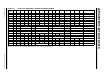
TABLE 9-1: TIMER1 REGISTER MAP
SFR Name Addr. Bit 15 Bit 14 Bit 13 Bit 12 Bit 11 Bit 10 Bit 9 Bit 8 Bit 7 Bit 6 Bit 5 Bit 4 Bit 3 Bit 2 Bit 1 Bit 0 Reset State
TMR1 0100 Timer1 Register uuuu uuuu uuuu uuuu
PR1 0102 Period Register 1 1111 1111 1111 1111
T1CON 0104 TON
—TSIDL— — — — — — TGATE TCKPS1 TCKPS0 — TSYNC TCS — 0000 0000 0000 0000
Legend: u = uninitialized bit; — = unimplemented bit, read as ‘0’
Note: Refer to the “dsPIC30F Family Reference Manual” (DS70046) for descriptions of register bit fields.