
Datasheet


© 2010 Microchip Technology Inc. DS70139G-page 73
dsPIC30F2011/2012/3012/3013
9.0 TIMER1 MODULE
This section describes the 16-bit general purpose
Timer1 module and associated operational modes.
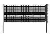
Figure 9-1 depicts the simplified block diagram of the
16-bit Timer1 module. The following sections provide
detailed descriptions including setup and Control
registers, along with associated block diagrams for the
operational modes of the timers.
The Timer1 module is a 16-bit timer that serves as the
time counter for the real-time clock or operates as a
free-running interval timer/counter. The 16-bit timer has
the following modes:
• 16-bit Timer
• 16-bit Synchronous Counter
• 16-bit Asynchronous Counter
These operational characteristics are supported:
• Timer gate operation
• Selectable prescaler settings
• Timer operation during CPU Idle and Sleep
modes
• Interrupt on 16-bit Period register match or falling
edge of external gate signal
These operating modes are determined by setting the
appropriate bit(s) in the 16-bit SFR, T1CON. Figure 9-1
presents a block diagram of the 16-bit timer module.
16-bit Timer Mode: In the 16-bit Timer mode, the timer
increments on every instruction cycle up to a match
value preloaded into the Period register PR1, then
resets to ‘0’ and continues to count.
When the CPU goes into the Idle mode, the timer stops
incrementing unless the TSIDL (T1CON<13>) bit = 0.
If TSIDL = 1, the timer module logic resumes the incre-
menting sequence on termination of CPU Idle mode.
16-bit Synchronous Counter Mode: In the 16-bit
Synchronous Counter mode, the timer increments on
the rising edge of the applied external clock signal
which is synchronized with the internal phase clocks.
The timer counts up to a match value preloaded in PR1,
then resets to ‘0’ and continues.
When the CPU goes into the Idle mode, the timer stops
incrementing unless the respective TSIDL bit = 0. If
TSIDL = 1, the timer module logic resumes the
incrementing sequence upon termination of the CPU
Idle mode.
16-bit Asynchronous Counter Mode: In the 16-bit
Asynchronous Counter mode, the timer increments on
every rising edge of the applied external clock signal.
The timer counts up to a match value preloaded in PR1,
then resets to ‘0’ and continues.
When the timer is configured for the Asynchronous
mode of operation and the CPU goes into the Idle
mode, the timer stops incrementing if TSIDL = 1.
FIGURE 9-1: 16-BIT TIMER1 MODULE BLOCK DIAGRAM
Note: This data sheet summarizes features of
this group of dsPIC30F devices and is not
intended to be a complete reference
source. For more information on the CPU,
peripherals, register descriptions and
general device functionality, refer to the
“dsPIC30F Family Reference Manual”
(DS70046).
TON
Sync
SOSCI
SOSCO/
PR1
T1IF
Equal
Comparator x 16
TMR1
Reset
LPOSCEN
Event Flag
1
0
TSYNC
Q
Q
D
CK
TGATE
TCKPS<1:0>
Prescaler
1, 8, 64, 256
2
TGATE
T
CY
1
0
T1CK
TCS
1 x
0 1
TGATE
0 0
Gate
Sync