
Datasheet


© 2010 Microchip Technology Inc. DS70139G-page 23
dsPIC30F2011/2012/3012/3013
2.4 DSP Engine
The DSP engine consists of a high-speed 17-bit x
17-bit multiplier, a barrel shifter and a 40-bit
adder/subtracter (with two target accumulators, round
and saturation logic).
The DSP engine also has the capability to perform
inherent accumulator-to-accumulator operations,
which require no additional data. These instructions are
ADD, SUB and NEG.
The dsPIC30F is a single-cycle instruction flow
architecture, therefore, concurrent operation of the
DSP engine with MCU instruction flow is not possible.
However, some MCU ALU and DSP engine resources
may be used concurrently by the same instruction
(e.g., ED, EDAC). See Table 2-2.
The DSP engine has several options selected through
various bits in the CPU Core Configuration register
(CORCON), which are:
1. Fractional or integer DSP multiply (IF).
2. Signed or unsigned DSP multiply (US).
3. Conventional or convergent rounding (RND).
4. Automatic saturation on/off for ACCA (SATA).
5. Automatic saturation on/off for ACCB (SATB).
6. Automatic saturation on/off for writes to data
memory (SATDW).
7. Accumulator Saturation mode selection
(ACCSAT).
A block diagram of the DSP engine is shown in
Figure 2-2.
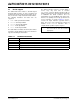
TABLE 2-2: DSP INSTRUCTION
SUMMARY
Instruction
Algebraic
Operation
ACC WB?
CLR A = 0 Yes
ED A = (x – y)
2
No
EDAC A = A + (x – y)
2
No
MAC A = A + (x * y) Yes
MAC A = A + x
2
No
MOVSAC No change in A Yes
MPY A = x • y No
MPY.N A = – x • y No
MSC A = A – x • y Yes
Note: For CORCON layout, see Table 3-3.