
Datasheet


© 2010 Microchip Technology Inc. DS70139G-page 165
dsPIC30F2011/2012/3012/3013
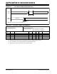
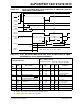
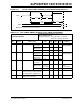
FIGURE 20-6: RESET, WATCHDOG TIMER, OSCILLATOR START-UP TIMER AND POWER-UP
TIMER TIMING CHARACTERISTICS
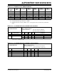
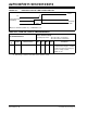
TABLE 20-21: RESET, WATCHDOG TIMER, OSCILLATOR START-UP TIMER, POWER-UP TIMER
AND BROWN-OUT RESET TIMING REQUIREMENTS
AC CHARACTERISTICS
Standard Operating Conditions: 2.5V to 5.5V
(unless otherwise stated)
Operating temperature -40°C ≤ TA ≤ +85°C for Industrial
-40°C ≤ TA ≤ +125°C for Extended
Param
No.
Symbol Characteristic
(1)
Min Typ
(2)
Max Units Conditions
SY10 TmcL MCLR Pulse Width (low) 2 — — μs -40°C to +85°C
SY11 TPWRT Power-up Timer Period 2
10
43
4
16
64
8
32
128
ms -40°C to +85°C, VDD =
5V
User programmable
SY12 TPOR Power On Reset Delay 3 10 30 μs -40°C to +85°C
SY13 T
IOZ I/O high impedance from MCLR
Low or Watchdog Timer Reset
—0.81.0μs
SY20 T
WDT1
T
WDT2
TWDT3
Watchdog Timer Time-out Period
(No Prescaler)
1.1
1.2
1.3
2.0
2.0
2.0
6.6
5.0
4.0
ms
ms
ms
V
DD = 2.5V
V
DD = 3.3V, ±10%
VDD = 5V, ±10%
SY25 TBOR Brown-out Reset Pulse Width
(3)
100 — — μsVDD ≤ VBOR (D034)
SY30 T
OST Oscillation Start-up Timer Period — 1024 TOSC ——TOSC = OSC1 period
SY35 T
FSCM Fail-Safe Clock Monitor Delay — 500 900 μs -40°C to +85°C
Note 1: These parameters are characterized but not tested in manufacturing.
2: Data in “Typ” column is at 5V, 25°C unless otherwise stated.
3: Refer to Figure 20-2 and Table 20-11 for BOR.
VDD
MCLR
Internal
POR
PWRT
Time-out
OSC
Time-out
Internal
RESET
Watchdog
Timer
RESET
SY11
SY10
SY20
SY13
I/O Pins
SY13
Note: Refer to Figure 20-3 for load conditions.
FSCM
Delay
SY35
SY30
SY12