
Datasheet


© 2010 Microchip Technology Inc. DS70139G-page 163
dsPIC30F2011/2012/3012/3013
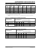
TABLE 20-17: INTERNAL CLOCK TIMING EXAMPLES
Clock
Oscillator
Mode
F
OSC
(MHz)
(1)
TCY (μsec)
(2)
MIPS
(3)
w/o PLL
MIPS
(3)
w PLL x4
MIPS
(3)
w PLL x8
MIPS
(3)
w PLL x16
EC 0.200 20.0 0.05 — — —
4 1.0 1.0 4.0 8.0 16.0
10 0.4 2.5 10.0 20.0 —
25 0.16 6.25 — — —
XT 4 1.0 1.0 4.0 8.0 16.0
10 0.4 2.5 10.0 20.0 —
Note 1: Assumption: Oscillator Postscaler is divide by 1.
2: Instruction Execution Cycle Time: T
CY = 1/MIPS.
3: Instruction Execution Frequency: MIPS = (FOSC * PLLx)/4 [since there are 4 Q clocks per instruction
cycle].
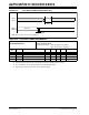
TABLE 20-18: AC CHARACTERISTICS: INTERNAL FRC ACCURACY
AC CHARACTERISTICS
Standard Operating Conditions: 2.5V to 5.5V
(unless otherwise stated)
Operating temperature -40°C ≤ T
A ≤ +85°C for Industrial
-40°C ≤ T
A ≤ +125°C for Extended
Param
No.
Characteristic Min Typ Max Units Conditions
Internal FRC Accuracy @ FRC Freq. = 7.37 MHz
(1)
OS63 FRC — — ±2.00 % -40°C ≤ TA ≤ +85°C VDD = 3.0-5.5V
— — ±5.00 % -40°C ≤ T
A ≤ +125°C VDD = 3.0-5.5V
Note 1: Frequency calibrated at 7.372 MHz ±2%, 25°C and 5V. TUN bits (OSCCON<3:0>) can be used to
compensate for temperature drift.
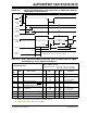
TABLE 20-19: AC CHARACTERISTICS: INTERNAL LPRC ACCURACY
AC CHARACTERISTICS
Standard Operating Conditions: 2.5V to 5.5V
(unless otherwise stated)
Operating temperature -40°C ≤ TA ≤ +85°C for Industrial
-40°C ≤ T
A ≤ +125°C for Extended
Param
No.
Characteristic Min Typ Max Units Conditions
LPRC @ Freq. = 512 kHz
(1)
OS65A -50 — +50 % VDD = 5.0V, ±10%
OS65B -60 — +60 % VDD = 3.3V, ±10%
OS65C -70 — +70 % V
DD = 2.5V
Note 1: Change of LPRC frequency as V
DD changes.