
Datasheet


dsPIC30F2011/2012/3012/3013
DS70139G-page 132 © 2010 Microchip Technology Inc.
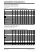
Table 17-5 shows the Reset conditions for the RCON
register. Since the control bits within the RCON register
are R/W, the information in the table means that all the
bits are negated prior to the action specified in the
condition column.
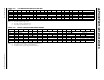
TABLE 17-5: INITIALIZATION CONDITION FOR RCON REGISTER: CASE 1
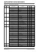
Table 17-6 shows a second example of the bit
conditions for the RCON register. In this case, it is not
assumed the user has set/cleared specific bits prior to
action specified in the condition column.
TABLE 17-6: INITIALIZATION CONDITION FOR RCON REGISTER: CASE 2
Condition
Program
Counter
TRAPR IOPUWR EXTR SWR WDTO IDLE SLEEP POR BOR
Power-on Reset 0x000000 000000011
Brown-out Reset 0x000000 000000001
MCLR
Reset during normal
operation
0x000000 001000000
Software Reset during
normal operation
0x000000 000100000
MCLR
Reset during Sleep 0x000000 001000100
MCLR
Reset during Idle 0x000000 001001000
WDT Time-out Reset 0x000000 000010000
WDT Wake-up PC + 2 000010100
Interrupt Wake-up from
Sleep
PC + 2
(1)
000000100
Clock Failure Trap 0x000004 000000000
Trap Reset 0x000000 100000000
Illegal Operation Trap 0x000000 010000000
Note 1: When the wake-up is due to an enabled interrupt, the PC is loaded with the corresponding interrupt vector.
Condition
Program
Counter
TRAPR IOPUWR EXTR SWR WDTO IDLE SLEEP POR BOR
Power-on Reset 0x000000 000000011
Brown-out Reset 0x000000 uuuuuuu01
MCLR
Reset during normal
operation
0x000000 uu10000uu
Software Reset during
normal operation
0x000000 uu01000uu
MCLR
Reset during Sleep 0x000000 uu1u001uu
MCLR
Reset during Idle 0x000000 uu1u010uu
WDT Time-out Reset 0x000000 uu00100uu
WDT Wake-up PC + 2 uuuu1u1uu
Interrupt Wake-up from
Sleep
PC + 2
(1)
uuuuuu1uu
Clock Failure Trap 0x000004 uuuuuuuuu
Trap Reset
0x000000 1uuuuuuuu
Illegal Operation Reset
0x000000 u1uuuuuuu
Legend: u = unchanged
Note 1: When the wake-up is due to an enabled interrupt, the PC is loaded with the corresponding interrupt vector.