
Datasheet


© 2010 Microchip Technology Inc. DS70139G-page 127
dsPIC30F2011/2012/3012/3013
17.2.3 LP OSCILLATOR CONTROL
Enabling the LP oscillator is controlled with two elements:
• The current oscillator group bits COSC<2:0>.
• The LPOSCEN bit (OSCCON register).
The LP oscillator is on (even during Sleep mode) if
LPOSCEN = 1. The LP oscillator is the device clock if:
•COSC<2:0> = 000 (LP selected as main osc.) and
• LPOSCEN = 1
Keeping the LP oscillator on at all times allows for a fast
switch to the 32 kHz system clock for lower power oper-
ation. Returning to the faster main oscillator will still
require a start-up time
17.2.4 PHASE LOCKED LOOP (PLL)
The PLL multiplies the clock which is generated by the
primary oscillator or Fast RC oscillator. The PLL is
selectable to have either gains of x4, x8, and x16. Input
and output frequency ranges are summarized in
Table 17-3.
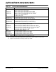
TABLE 17-3: PLL FREQUENCY RANGE
The PLL features a lock output which is asserted when
the PLL enters a phase locked state. Should the loop
fall out of lock (e.g., due to noise), the lock signal will be
rescinded. The state of this signal is reflected in the
read-only LOCK bit in the OSCCON register.
17.2.5 FAST RC OSCILLATOR (FRC)
The FRC oscillator is a fast (7.37 MHz ±2% nominal)
internal RC oscillator. This oscillator is intended to
provide reasonable device operating speeds without
the use of an external crystal, ceramic resonator, or RC
network. The FRC oscillator can be used with the PLL
to obtain higher clock frequencies.
The dsPIC30F operates from the FRC oscillator when-
ever the current oscillator selection control bits in the
OSCCON register (OSCCON<14:12>) are set to ‘001’.
The four bit field specified by TUN<3:0> (OSCTUN
<3:0>) allows the user to tune the internal fast RC
oscillator (nominal 7.37 MHz). The user can tune the
FRC oscillator within a range of +10.5% (840 kHz)
and -12% (960 kHz) in steps of 1.50% around the
factory calibrated setting, as shown in Table 17-4.
If OSCCON<14:12> are set to ‘111’ and FPR<4:0> are
set to ‘00001’, ‘01010’ or ‘00011’, a PLL multiplier of
4, 8 or 16 (respectively) is applied.
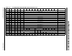
TABLE 17-4: FRC TUNING
17.2.6 LOW-POWER RC OSCILLATOR (LPRC)
The LPRC oscillator is a component of the Watchdog
Timer (WDT) and oscillates at a nominal frequency of
512 kHz. The LPRC oscillator is the clock source for
the Power-up Timer (PWRT) circuit, WDT and clock
monitor circuits. It may also be used to provide a
low-frequency clock source option for applications
where power consumption is critical and timing
accuracy is not required.
The LPRC oscillator is always enabled at a Power-on
Reset because it is the clock source for the PWRT.
After the PWRT expires, the LPRC oscillator will remain
on if one of the following is true:
• The Fail-Safe Clock Monitor is enabled
• The WDT is enabled
• The LPRC oscillator is selected as the system
clock via the COSC<2:0> control bits in the
OSCCON register
If one of the above conditions is not true, the LPRC will
shut-off after the PWRT expires.
F
IN
PLL
Multiplier
F
OUT
4 MHz-10 MHz x4 16 MHz-40 MHz
4 MHz-10 MHz x8 32 MHz-80 MHz
4 MHz-7.5 MHz x16 64 MHz-120 MHz
Note: OSCTUN functionality has been provided
to help customers compensate for
temperature effects on the FRC frequency
over a wide range of temperatures. The
tuning step size is an approximation and is
neither characterized nor tested.
Note: When a 16x PLL is used, the FRC fre-
quency must not be tuned to a frequency
greater than 7.5 MHz.
TUN<3:0>
Bits
FRC Frequency
0111 + 10.5%
0110 + 9.0%
0101 + 7.5%
0100 + 6.0%
0011 + 4.5%
0010 + 3.0%
0001 + 1.5%
0000 Center Frequency (oscillator is
running at calibrated frequency)
1111 - 1.5%
1110 - 3.0%
1101 - 4.5%
1100 - 6.0%
1011 - 7.5%
1010 - 9.0%
1001 - 10.5%
1000 - 12.0%
Note 1: OSC2 pin function is determined by the
Primary Oscillator mode selection
(FPR<4:0>).
2: OSC1 pin cannot be used as an I/O pin
even if the secondary oscillator or an
internal clock source is selected at all
times.