
Datasheet


dsPIC30F2011/2012/3012/3013
DS70139G-page 116 © 2010 Microchip Technology Inc.
16.7 ADC Speeds
The dsPIC30F 12-bit ADC specifications permit a
maximum of 200 ksps sampling rate. Table 1 6-1
summarizes the conversion speeds for the dsPIC30F
12-bit ADC and the required operating conditions.
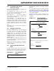
Figure 16-2 depicts the recommended circuit for the
conversion rates above 200 ksps. The dsPIC30F2011
is shown as an example.
FIGURE 16-2: ADC VOLTAGE REFERENCE SCHEMATIC
TABLE 16-1: 12-BIT ADC EXTENDED CONVERSION RATES
dsPIC30F 12-bit ADC Conversion Rates
Speed
TAD
Minimum
Sampling
Time Min
R
s
Max VDD Temperature Channel Configuration
Up to 200
ksps
(1)
334 ns 1 TAD 2.5 kΩ 4.5V
to
5.5V
-40°C to +85°C
Up to 100
ksps
668 ns 1 T
AD 2.5 kΩ 3.0V
to
5.5V
-40°C to +125°C
Note 1: External V
REF- and VREF+ pins must be used for correct operation. See Figure 16-2 for recommended
circuit.
VREF-VREF+
ADC
ANx
S/H
CH
X
VREF-VREF+
ADC
ANx
S/H
CH
X
ANx or VREF-
or
AV
SS
or
AV
DD
VDD
VDD
VDD
C8
1 μF
VDD
C7
0.1 μF
VDD
C6
0.01 μF
AVDD
C5
1 μF
AVDD
C4
0.1 μF
AVDD
C3
0.01 μF
See Note 1:
Note 1: Ensure adequate bypass capacitors are provided on each V
DD pin.
VREF-
27
26
AV
DD
VSS
23
22
8
9
V
DD
11
12
13
14
1
2
3
4
V
SS
6
7
21
20
19
18
V
DD
VSS
15
dsPIC30F2011
VDD
R1
10
VDD
R2
10
C2
0.1 μF
C1
0.01 μF