
Datasheet


© 2010 Microchip Technology Inc. DS70139G-page 115
dsPIC30F2011/2012/3012/3013
16.4 Programming the Start of
Conversion Trigger
The conversion trigger will terminate acquisition and
start the requested conversions.
The SSRC<2:0> bits select the source of the
conversion trigger. The SSRC bits provide for up to four
alternate sources of conversion trigger.
When SSRC<2:0> = 000, the conversion trigger is
under software control. Clearing the SAMP bit will
cause the conversion trigger.
When SSRC<2:0> = 111 (Auto-Start mode), the
conversion trigger is under A/D clock control. The
SAMC bits select the number of A/D clocks between
the start of acquisition and the start of conversion. This
provides the fastest conversion rates on multiple
channels. SAMC must always be at least one clock
cycle.
Other trigger sources can come from timer modules or
external interrupts.
16.5 Aborting a Conversion
Clearing the ADON bit during a conversion will abort
the current conversion and stop the sampling
sequencing until the next sampling trigger. The
ADCBUF will not be updated with the partially
completed A/D conversion sample. That is, the
ADCBUF will continue to contain the value of the last
completed conversion (or the last value written to the
ADCBUF register).
If the clearing of the ADON bit coincides with an
auto-start, the clearing has a higher priority and a new
conversion will not start.
After the A/D conversion is aborted, a 2 T
AD wait is
required before the next sampling may be started by
setting the SAMP bit.
16.6 Selecting the ADC Conversion
Clock
The ADC conversion requires 14 TAD. The source of
the ADC conversion clock is software selected, using a
6-bit counter. There are 64 possible options for TAD.
EQUATION 16-1: ADC CONVERSION
CLOCK
The internal RC oscillator is selected by setting the
ADRC bit.
For correct ADC conversions, the ADC conversion
clock (T
AD) must be selected to ensure a minimum TAD
time of 334 nsec (for VDD = 5V). Refer to Section 20.0
“Electrical Characteristics” for minimum TAD under
other operating conditions.
Example 16-1 shows a sample calculation for the
ADCS<5:0> bits, assuming a device operating speed
of 30 MIPS.
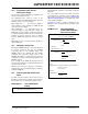
EXAMPLE 16-1: ADC CONVERSION
CLOCK AND SAMPLING
RATE CALCULATION
TAD = TCY * (0.5*(ADCS<5:0> + 1))
Minimum TAD = 334 nsec
ADCS<5:0> = 2 – 1
T
AD
TCY
TCY = 33 .33 nsec (30 MIPS)
= 2 • – 1
334 nsec
33.33 nsec
= 19.04
Therefore,
Set ADCS<5:0> = 19
Actual T
AD = (ADCS<5:0> + 1)
T
CY
2
= (19 + 1)
33.33 nsec
2
= 334 nsec
If SSRC<2:0> = ‘111’ and SAMC<4:0> = ‘00001’
Since,
Sampling Time = Acquisition Time + Conversion Time
= 1 T
AD + 14 TAD
= 15 x 334 nsec
Therefore,
Sampling Rate =
= ~200 kHz
1
(15 x 334 nsec)