
Datasheet


© 2010 Microchip Technology Inc. DS70139G-page 105
dsPIC30F2011/2012/3012/3013
15.0 UNIVERSAL ASYNCHRONOUS
RECEIVER TRANSMITTER
(UART) MODULE
This section describes the Universal Asynchronous
Receiver/Transmitter Communications module. The
dsPIC30F2011/2012/3012 processors have one UART
module (UART1). The dsPIC30F3013 processor has
two UART modules (UART1 and UART2).
15.1 UART Module Overview
The key features of the UART module are:
• Full-duplex, 8 or 9-bit data communication
• Even, odd or no parity options (for 8-bit data)
• One or two Stop bits
• Fully integrated Baud Rate Generator with 16-bit
prescaler
• Baud rates range from 38 bps to 1.875 Mbps at a
30 MHz instruction rate
• 4-word deep transmit data buffer
• 4-word deep receive data buffer
• Parity, framing and buffer overrun error detection
• Support for interrupt only on address detect
(9th bit = 1)
• Separate transmit and receive interrupts
• Loopback mode for diagnostic support
• Alternate receive and transmit pins for UART1
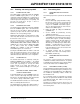
FIGURE 15-1: UART TRANSMITTER BLOCK DIAGRAM
Note: This data sheet summarizes features of
this group of dsPIC30F devices and is not
intended to be a complete reference
source. For more information on the CPU,
peripherals, register descriptions and
general device functionality, refer to the
“dsPIC30F Family Reference Manual”
(DS70046).
Write
Write
UTX8
UxTXREG Low Byte
Load TSR
Transmit Control
– Control TSR
– Control Buffer
– Generate Flags
– Generate Interrupt
Control and Status bits
UxTXIF
Data
‘
0’ (Start)
‘
1’ (Stop)
Parity
Parity
Generator
Transmit Shift Register (UxTSR)
16 Divider
Control
Signals
16x Baud Clock
from Baud Rate
Generator
Internal Data Bus
UTXBRK
UxTX
Note: x = 1 or 2.