dsPIC30F2011/2012/3012/3013 Data Sheet High-Performance, 16-bit Digital Signal Controllers © 2010 Microchip Technology Inc.
Note the following details of the code protection feature on Microchip devices: • Microchip products meet the specification contained in their particular Microchip Data Sheet. • Microchip believes that its family of products is one of the most secure families of its kind on the market today, when used in the intended manner and under normal conditions. • There are dishonest and possibly illegal methods used to breach the code protection feature.
dsPIC30F2011/2012/3012/3013 High-Performance, 16-bit Digital Signal Controllers Note: This data sheet summarizes features of this group of dsPIC30F devices and is not intended to be a complete reference source. For more information on the CPU, peripherals, register descriptions and general device functionality, refer to the “dsPIC30F Family Reference Manual” (DS70046).
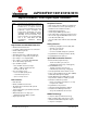
dsPIC30F2011/2012/3012/3013 dsPIC30F2011/2012/3012/3013 Sensor Family Input Cap Output Comp/Std PWM A/D 12-bit 200 Ksps I2C™ Timer 16-bit SPI EEPROM Bytes UART Program Memory dsPIC30F2011 18 12K 4K 1024 – 3 2 2 8 ch 1 1 1 dsPIC30F3012 18 24K 8K 2048 1024 3 2 2 8 ch 1 1 1 dsPIC30F2012 28 12K 4K 1024 – 3 2 2 10 ch 1 1 1 dsPIC30F3013 28 24K 8K 2048 1024 3 2 2 10 ch 2 1 1 1 2 3 4 5 6 7 8 9 18 17 16 15 14 13 12 11 10 AVDD AVSS AN6/SCK1/INT0/OCFA/RB6
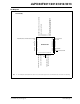
dsPIC30F2011/2012/3012/3013 Pin Diagrams 28 27 26 25 24 23 22 EMUC3/AN1/VREF-/CN3/RB1 EMUD3/AN0/VREF+/CN2/RB0 MCLR AVDD AVSS AN6/SCK1/INT0/OCFA/RB6 EMUD2/AN7/OC2/IC2/INT2/RB7 28-Pin QFN-S(1) dsPIC30F2011 8 9 10 11 12 13 14 1 2 3 4 5 6 7 21 20 19 18 17 16 15 NC NC NC NC VDD VSS PGC/EMUC/AN5/U1RX/SDI1/SDA/CN7/RB5 EMUD1/SOSC1/T2CK/U1ATX/CN1/RC13 EMUC1/SOSCO/T1CK/U1ARX/CN0/RC14 VDD NC EMUC2/OC1/IC1/INT1/RD0 NC PGD/EMUD/AN4/U1TX/SDO1/SCL/CN6/RB4 AN2/SS1/LVDIN/CN4/RB2 AN3/CN5/RB3 NC NC VSS OSC1/CLKI OSC
dsPIC30F2011/2012/3012/3013 Pin Diagrams 28 27 26 25 24 23 22 EMUC3/AN1/VREF-/CN3/RB1 EMUD3/AN0/VREF+/CN2/RB0 MCLR AVDD AVSS AN6/OCFA/RB6 EMUD2/AN7/RB7 28-Pin QFN-S(1) dsPIC30F2012 8 9 10 11 12 13 14 1 2 3 4 5 6 7 21 20 19 18 17 16 15 AN8/OC1/RB8 AN9/OC2/RB9 CN17/RF4 CN18/RF5 VDD VSS PGC/EMUC/U1RX/SDI1/SDA/RF2 EMUD1/SOSCI/T2CK/U1ATX/CN1/RC13 EMUC1/SOSCO/T1CK/U1ARX/CN0/RC14 VDD IC2/INT2/RD9 EMUC2/IC1/INT1/RD8 SCK1/INT0/RF6 PGD/EMUD/U1TX/SDO1/SCL/RF3 AN2/SS1/LVDIN/CN4/RB2 AN3/CN5/RB3 AN4/CN6/RB4 AN5
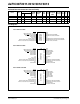
dsPIC30F2011/2012/3012/3013 Pin Diagram PGD/EMUD/AN4/U1TX/SDO1/SCL/CN6/RB4 NC EMUC2/OC1/IC1/INT1/RD0 NC NC NC NC NC VDD EMUC1/SOSCO/T1CK/U1ARX/CN0/RC14 EMUD1/SOSCI/T2CK/U1ATX/CN1/RC13 44-Pin QFN(1) 44 43 42 41 40 39 38 37 36 35 34 PGC/EMUC/AN5/U1RX/SDI1/SDA/CN7/RB5 VSS NC VDD NC NC NC NC NC NC NC 1 2 3 4 5 6 7 8 9 10 11 dsPIC30F3012 33 32 31 30 29 28 27 26 25 24 23 OSC2/CLKO/RC15 OSC1/CLKI VSS VSS NC NC NC NC AN3/CN5/RB3 NC AN2/SS1/LVDIN/CN4/RB2 EMUD2/AN7/OC2/IC2/INT2/RB7 NC AN6/SCK1/INT0/OCFA/RB6 N
dsPIC30F2011/2012/3012/3013 Pin Diagrams 44 43 42 41 40 39 38 37 36 35 34 PGD/EMUD/U1TX/SDO1/SCL/RF3 SCK1/INT0/RF6 EMUC2/IC1/INT1/RD8 NC NC NC NC IC2/INT2/RD9 VDD EMUC1/SOSCO/T1CK/U1ARX/CN0/RC14 EMUD1/SOSCI/T2CK/U1ATX/CN1/RC13 44-Pin QFN(1) 1 2 3 4 5 6 7 8 9 10 11 dsPIC30F3013 33 32 31 30 29 28 27 26 25 24 23 OSC2/CLKO/RC15 OSC1/CLKI VSS VSS NC NC AN5/CN7/RB5 AN4/CN6/RB4 AN3/CN5/RB3 NC AN2/SS1/LVDIN/CN4/RB2 EMUD2/AN7/RB7 NC AN6/OCFA/RB6 NC AVSS AVDD MCLR EMUD3/AN0/VREF+/CN2/RB0 EMUC3/AN1/VREF-/CN3/R
dsPIC30F2011/2012/3012/3013 Table of Contents 1.0 Device Overview ........................................................................................................................................................................ 11 2.0 CPU Architecture Overview........................................................................................................................................................ 19 3.0 Memory Organization .................................................................
dsPIC30F2011/2012/3012/3013 NOTES: DS70139G-page 10 © 2010 Microchip Technology Inc.
dsPIC30F2011/2012/3012/3013 1.0 Note: DEVICE OVERVIEW This data sheet summarizes features of this group of dsPIC30F devices and is not intended to be a complete reference source. For more information on the CPU, peripherals, register descriptions and general device functionality, refer to the “dsPIC30F Family Reference Manual” (DS70046). For more information on the device instruction set and programming, refer to the “16-bit MCU and DSC Programmer’s Reference Manual” (DS70157).
dsPIC30F2011/2012/3012/3013 FIGURE 1-1: dsPIC30F2011 BLOCK DIAGRAM Y Data Bus X Data Bus 16 16 Interrupt Controller PSV & Table Data Access 24 Control Block 8 Data Latch Y Data RAM (512 bytes) Address Latch 16 24 Address Latch 16 16 EMUD3/AN0/VREF+/CN2/RB0 EMUC3/AN1/VREF-/CN3/RB1 AN2/SS1/LVDIN/CN4/RB2 AN3/CN5/RB3 PGD/EMUD/AN4/U1TX/SDO1/SCL/CN6/RB4 PGC/EMUC/AN5/U1RX/SDI1/SDA/CN7/RB5 AN6/SCK1/INT0/OCFA/RB6 EMUD2/AN7/OC2/IC2/INT2/RB7 X RAGU X WAGU Y AGU PCU PCH PCL Program Counter Loop Stack Cont
dsPIC30F2011/2012/3012/3013 FIGURE 1-2: dsPIC30F2012 BLOCK DIAGRAM Y Data Bus X Data Bus 16 Interrupt Controller PSV & Table Data Access 24 Control Block 8 16 16 Data Latch Y Data RAM (512 bytes) Address Latch 16 24 Address Latch 16 16 EMUD3/AN0/VREF+/CN2/RB0 EMUC3/AN1/VREF-/CN3/RB1 AN2/SS1/LVDIN/CN4/RB2 AN3/CN5/RB3 AN4/CN6/RB4 AN5/CN7/RB5 AN6/OCFA/RB6 EMUD2/AN7/RB7 AN8/OC1/RB8 AN9/OC2/RB9 X RAGU X WAGU Y AGU PCU PCH PCL Program Counter Loop Stack Control Control Logic Logic Data Latch X Da
dsPIC30F2011/2012/3012/3013 FIGURE 1-3: dsPIC30F3012 BLOCK DIAGRAM Y Data Bus X Data Bus 16 16 Interrupt Controller PSV & Table Data Access 24 Control Block 8 Data Latch Y Data RAM (1 Kbytes) Address Latch 16 24 Address Latch Data EEPROM (1 Kbytes) 16 16 EMUD3/AN0/VREF+/CN2/RB0 EMUC3/AN1/VREF-/CN3/RB1 AN2/SS1/LVDIN/CN4/RB2 AN3/CN5/RB3 PGD/EMUD/AN4/U1TX/SDO1/SCL/CN6/RB4 PGC/EMUC/AN5/U1RX/SDI1/SDA/CN7/RB5 AN6/SCK1/INT0/OCFA/RB6 EMUD2/AN7/OC2/IC2/INT2/RB7 X RAGU X WAGU Y AGU PCU PCH PCL Program C
dsPIC30F2011/2012/3012/3013 FIGURE 1-4: dsPIC30F3013 BLOCK DIAGRAM Y Data Bus X Data Bus PSV & Table Data Access 24 Control Block 8 16 16 16 Interrupt Controller 16 24 Address Latch 16 16 EMUD3/AN0/VREF+/CN2/RB0 EMUC3/AN1/VREF-/CN3/RB1 AN2/SS1/LVDIN/CN4/RB2 AN3/CN5/RB3 AN4/CN6/RB4 AN5/CN7/RB5 AN6/OCFA/RB6 EMUD2/AN7/RB7 AN8/OC1/RB8 AN9/OC2/RB9 X RAGU X WAGU Y AGU PCU PCH PCL Program Counter Loop Stack Control Control Logic Logic Data Latch X Data RAM (1 Kbytes) Address Latch 16 16 24 Progra
dsPIC30F2011/2012/3012/3013 Table 1-1 provides a brief description of device I/O pinouts and the functions that may be multiplexed to a port pin. Multiple functions may exist on one port pin. When multiplexing occurs, the peripheral module’s functional requirements may force an override of the data direction of the port pin. TABLE 1-1: PINOUT I/O DESCRIPTIONS Pin Type Buffer Type AN0 - AN9 I Analog AVDD P P Positive supply for analog module. This pin must be connected at all times.
dsPIC30F2011/2012/3012/3013 TABLE 1-1: PINOUT I/O DESCRIPTIONS (CONTINUED) Pin Type Buffer Type SCL SDA I/O I/O ST ST SOSCO SOSCI O I — ST/CMOS T1CK T2CK I I ST ST Timer1 external clock input. Timer2 external clock input. U1RX U1TX U1ARX U1ATX U2RX U2TX I O I O I O ST — ST — ST — UART1 Receive. UART1 Transmit. UART1 Alternate Receive. UART1 Alternate Transmit. UART2 Receive. UART2 Transmit. VDD P — Positive supply for logic and I/O pins.
dsPIC30F2011/2012/3012/3013 NOTES: DS70139G-page 18 © 2010 Microchip Technology Inc.
dsPIC30F2011/2012/3012/3013 2.0 Note: CPU ARCHITECTURE OVERVIEW This data sheet summarizes features of this group of dsPIC30F devices and is not intended to be a complete reference source. For more information on the CPU, peripherals, register descriptions and general device functionality, refer to the “dsPIC30F Family Reference Manual” (DS70046). For more information on the device instruction set and programming, refer to the “16-bit MCU and DSC Programmer’s Reference Manual” (DS70157).
dsPIC30F2011/2012/3012/3013 The core does not support a multi-stage instruction pipeline. However, a single-stage instruction prefetch mechanism is used, which accesses and partially decodes instructions a cycle ahead of execution, in order to maximize available execution time. Most instructions execute in a single cycle with certain exceptions. The core features a vectored exception processing structure for traps and interrupts, with 62 independent vectors.
dsPIC30F2011/2012/3012/3013 FIGURE 2-1: PROGRAMMER’S MODEL D15 D0 W0/WREG PUSH.
dsPIC30F2011/2012/3012/3013 2.3 Divide Support The dsPIC DSC devices feature a 16/16-bit signed fractional divide operation, as well as 32/16-bit and 16/16-bit signed and unsigned integer divide operations, in the form of single instruction iterative divides. The following instructions and data sizes are supported: 1. 2. 3. 4. 5. DIVF - 16/16 signed fractional divide DIV.sd - 32/16 signed divide DIV.ud - 32/16 unsigned divide DIV.s - 16/16 signed divide DIV.
dsPIC30F2011/2012/3012/3013 2.4 DSP Engine The DSP engine consists of a high-speed 17-bit x 17-bit multiplier, a barrel shifter and a 40-bit adder/subtracter (with two target accumulators, round and saturation logic). The DSP engine also has the capability to perform inherent accumulator-to-accumulator operations, which require no additional data. These instructions are ADD, SUB and NEG.
dsPIC30F2011/2012/3012/3013 FIGURE 2-2: DSP ENGINE BLOCK DIAGRAM 40 40-bit Accumulator A 40-bit Accumulator B Carry/Borrow Out Carry/Borrow In 40 Saturate S a Round t 16 u Logic r a t e Adder Negate 40 40 40 Barrel Shifter 16 X Data Bus 40 Y Data Bus Sign-Extend 32 16 Zero Backfill 32 33 17-bit Multiplier/Scaler 16 16 To/From W Array DS70139G-page 24 © 2010 Microchip Technology Inc.
dsPIC30F2011/2012/3012/3013 2.4.1 MULTIPLIER The 17 x 17-bit multiplier is capable of signed or unsigned operation and can multiplex its output using a scaler to support either 1.31 fractional (Q31) or 32-bit integer results. Unsigned operands are zero-extended into the 17th bit of the multiplier input value. Signed operands are sign-extended into the 17th bit of the multiplier input value. The output of the 17 x 17-bit multiplier/scaler is a 33-bit value which is sign-extended to 40 bits.
dsPIC30F2011/2012/3012/3013 The SA and SB bits are modified each time data passes through the adder/subtracter but can only be cleared by the user. When set, they indicate that the accumulator has overflowed its maximum range (bit 31 for 32-bit saturation or bit 39 for 40-bit saturation) and will be saturated if saturation is enabled. When saturation is not enabled, SA and SB default to bit 39 overflow and thus indicate that a catastrophic overflow has occurred.
dsPIC30F2011/2012/3012/3013 2.4.2.4 Data Space Write Saturation 2.4.3 BARREL SHIFTER In addition to adder/subtracter saturation, writes to data space may also be saturated but without affecting the contents of the source accumulator. The data space write saturation logic block accepts a 16-bit, 1.15 fractional value from the round logic block as its input, together with overflow status from the original source (accumulator) and the 16-bit round adder.
dsPIC30F2011/2012/3012/3013 NOTES: DS70139G-page 28 © 2010 Microchip Technology Inc.
dsPIC30F2011/2012/3012/3013 3.0 Note: 3.1 MEMORY ORGANIZATION This data sheet summarizes features of this group of dsPIC30F devices and is not intended to be a complete reference source. For more information on the CPU, peripherals, register descriptions and general device functionality, refer to the “dsPIC30F Family Reference Manual” (DS70046). For more information on the device instruction set and programming, refer to the “16-bit MCU and DSC Programmer’s Reference Manual” (DS70157).
dsPIC30F2011/2012/3012/3013 FIGURE 3-1: PROGRAM SPACE MEMORY MAPS dsPIC30F2011/2012 Reset - GOTO Instruction Reset - Target Address dsPIC30F3012/3013 Reset - GOTO Instruction Reset - Target Address 000000 000002 000004 Interrupt Vector Table Interrupt Vector Table Vector Tables Reserved Vector Tables 00007E 000080 000084 Reserved 0000FE 000100 001FFE 002000 User Flash Program Memory (8K instructions) Reserved (Read ‘0’s) Reserved (Read ‘0’s) Data EEPROM (1 Kbyte) 7FFFFE 800000 F7FFFE F80000 F
dsPIC30F2011/2012/3012/3013 TABLE 3-1: PROGRAM SPACE ADDRESS CONSTRUCTION Program Space Address Access Space Access Type <23> <22:16> <15> <14:1> Instruction Access User TBLRD/TBLWT User (TBLPAG<7> = 0) TBLPAG<7:0> Data EA<15:0> TBLRD/TBLWT Configuration (TBLPAG<7> = 1) TBLPAG<7:0> Data EA<15:0> Program Space Visibility User FIGURE 3-2: <0> PC<22:1> 0 0 PSVPAG<7:0> 0 Data EA<14:0> DATA ACCESS FROM PROGRAM SPACE ADDRESS GENERATION 23 bits Using Program Counter Program Counter 0
dsPIC30F2011/2012/3012/3013 3.1.1 DATA ACCESS FROM PROGRAM MEMORY USING TABLE INSTRUCTIONS A set of table instructions are provided to move byte or word-sized data to and from program space. See Figure 3-4 and Figure 3-5. 1. This architecture fetches 24-bit wide program memory. Consequently, instructions are always aligned. However, as the architecture is modified Harvard, data can also be present in program space.
dsPIC30F2011/2012/3012/3013 FIGURE 3-4: PROGRAM DATA TABLE ACCESS (MSB) TBLRDH.W PC Address 0x000000 0x000002 0x000004 0x000006 23 16 8 0 00000000 00000000 00000000 00000000 TBLRDH.B (Wn<0> = 0) Program Memory ‘Phantom’ Byte (read as ‘0’) 3.1.2 TBLRDH.B (Wn<0> = 1) DATA ACCESS FROM PROGRAM MEMORY USING PROGRAM SPACE VISIBILITY The upper 32 Kbytes of data space may optionally be mapped into any 16K word program space page.
dsPIC30F2011/2012/3012/3013 FIGURE 3-5: DATA SPACE WINDOW INTO PROGRAM SPACE OPERATION Data Space Program Space 0x0000 PSVPAG(1) 0x00 8 15 EA<15> = 0 Data 16 Space 15 EA EA<15> = 1 0x000000 0x8000 15 Address Concatenation 23 23 15 0 0x001200 Upper Half of Data Space is Mapped into Program Space 0x001FFF 0xFFFF Data Read BSET MOV MOV MOV CORCON,#2 ; Set PSV bit #0x0, W0 ; Set PSVPAG register W0, PSVPAG 0x9200, W0 ; Access program memory location ; using a data space access Note 1: PSVPAG is an
dsPIC30F2011/2012/3012/3013 3.2 Data Address Space The core has two data spaces. The data spaces can be considered either separate (for some DSP instructions), or as one unified linear address range (for MCU instructions). The data spaces are accessed using two Address Generation Units (AGUs) and separate data paths. 3.2.1 DATA SPACE MEMORY MAP The data space memory is split into two blocks, X and Y data space.
dsPIC30F2011/2012/3012/3013 FIGURE 3-7: dsPIC30F3012/3013 DATA SPACE MEMORY MAP MSB Address 16 bits MSB 2 Kbyte SFR Space 2 Kbyte SRAM Space LSB 0x0000 0x0001 SFR Space 0x07FE 0x0800 0x07FF 0x0801 0x0BFF 0x0C01 X Data RAM (X) 8 Kbyte Near Data Space 0x0BFE 0x0C00 Y Data RAM (Y) 0x0FFF 0x1001 0x0FFE 0x1000 0x1FFF 0x1FFE 0x8001 0x8000 X Data Unimplemented (X) Optionally Mapped into Program Memory 0xFFFF DS70139G-page 36 LSB Address 0xFFFE © 2010 Microchip Technology Inc.
dsPIC30F2011/2012/3012/3013 DATA SPACE FOR MCU AND DSP (MAC CLASS) INSTRUCTIONS EXAMPLE SFR SPACE SFR SPACE X SPACE FIGURE 3-8: Y SPACE UNUSED X SPACE (Y SPACE) X SPACE UNUSED UNUSED Non-MAC Class Ops (Read/Write) MAC Class Ops (Write) Indirect EA using any W © 2010 Microchip Technology Inc.
dsPIC30F2011/2012/3012/3013 3.2.2 DATA SPACES 3.2.3 The X data space is used by all instructions and supports all addressing modes. There are separate read and write data buses. The X read data bus is the return data path for all instructions that view data space as combined X and Y address space. It is also the X address space data path for the dual operand read instructions (MAC class). The X write data bus is the only write path to data space for all instructions.
dsPIC30F2011/2012/3012/3013 A Sign-Extend (SE) instruction is provided to allow users to translate 8-bit signed data to 16-bit signed values. Alternatively, for 16-bit unsigned data, users can clear the MSB of any W register by executing a Zero-Extend (ZE) instruction on the appropriate address. Although most instructions are capable of operating on word or byte data sizes, it should be noted that some instructions, including the DSP instructions, operate only on words. 3.2.
SFR Name CORE REGISTER MAP Address (Home) Bit 15 Bit 14 Bit 13 Bit 12 Bit 11 Bit 10 Bit 9 Bit 8 Bit 7 Bit 6 Bit 5 Bit 4 Bit 3 Bit 2 Bit 1 Bit 0 Reset State W0 0000 W0/WREG 0000 0000 0000 0000 W1 0002 W1 0000 0000 0000 0000 W2 0004 W2 0000 0000 0000 0000 W3 0006 W3 0000 0000 0000 0000 W4 0008 W4 0000 0000 0000 0000 W5 000A W5 0000 0000 0000 0000 W6 000C W6 0000 0000 0000 0000 W7 000E W7 0000 0000 0000 0000 W8 0010 W8 0000 0000 0000 0000 W9 0012 W9 00
© 2010 Microchip Technology Inc.
dsPIC30F2011/2012/3012/3013 NOTES: DS70139G-page 42 © 2010 Microchip Technology Inc.
dsPIC30F2011/2012/3012/3013 4.0 Note: ADDRESS GENERATOR UNITS This data sheet summarizes features of this group of dsPIC30F devices and is not intended to be a complete reference source. For more information on the CPU, peripherals, register descriptions and general device functionality, refer to the “dsPIC30F Family Reference Manual” (DS70046). For more information on the device instruction set and programming, refer to the “16-bit MCU and DSC Programmer’s Reference Manual” (DS70157).
dsPIC30F2011/2012/3012/3013 4.1.3 MOVE AND ACCUMULATOR INSTRUCTIONS Move instructions and the DSP accumulator class of instructions provide a greater degree of addressing flexibility than other instructions. In addition to the addressing modes supported by most MCU instructions, move and accumulator instructions also support Register Indirect with Register Offset Addressing mode, also referred to as Register Indexed mode.
dsPIC30F2011/2012/3012/3013 4.2.1 START AND END ADDRESS 4.2.2 The Modulo Addressing scheme requires that a starting and an ending address be specified and loaded into the 16-bit Modulo Buffer Address registers: XMODSRT, XMODEND, YMODSRT and YMODEND (see Table 3-3). Note: Y space Modulo Addressing EA calculations assume word-sized data (LSb of every EA is always clear). The length of a circular buffer is not directly specified.
dsPIC30F2011/2012/3012/3013 4.2.3 MODULO ADDRESSING APPLICABILITY Modulo Addressing can be applied to the Effective Address (EA) calculation associated with any W register. It is important to realize that the address boundaries check for addresses less than, or greater than the upper (for incrementing buffers), and lower (for decrementing buffers) boundary addresses (not just equal to). Address changes may, therefore, jump beyond boundaries and still be adjusted correctly. Note: 4.
dsPIC30F2011/2012/3012/3013 FIGURE 4-2: BIT-REVERSED ADDRESS EXAMPLE Sequential Address b15 b14 b13 b12 b11 b10 b9 b8 b7 b6 b5 b4 b3 b2 b1 0 Bit Locations Swapped Left-to-Right Around Center of Binary Value b15 b14 b13 b12 b11 b10 b9 b8 b7 b6 b5 b1 b2 b3 b4 0 Bit-Reversed Address Pivot Point XB = 0x0008 for a 16-word Bit-Reversed Buffer TABLE 4-2: BIT-REVERSED ADDRESS SEQUENCE (16-ENTRY) Normal Address Bit-Reversed Address A3 A2 A1 A0 Decimal A3 A2 A1 A0 Decimal 0 0 0 0 0 0 0
dsPIC30F2011/2012/3012/3013 NOTES: DS70139G-page 48 © 2010 Microchip Technology Inc.
dsPIC30F2011/2012/3012/3013 5.0 FLASH PROGRAM MEMORY Note: 5.2 This data sheet summarizes features of this group of dsPIC30F devices and is not intended to be a complete reference source. For more information on the CPU, peripherals, register descriptions and general device functionality, refer to the “dsPIC30F Family Reference Manual” (DS70046). For more information on the device instruction set and programming, refer to the “16-bit MCU and DSC Programmer’s Reference Manual” (DS70157).
dsPIC30F2011/2012/3012/3013 5.4 RTSP Operation The dsPIC30F Flash program memory is organized into rows and panels. Each row consists of 32 instructions or 96 bytes. Each panel consists of 128 rows or 4K x 24 instructions. RTSP allows the user to erase one row (32 instructions) at a time and to program four instructions at one time. RTSP may be used to program multiple program memory panels, but the table pointer must be changed at each panel boundary.
dsPIC30F2011/2012/3012/3013 5.6 Programming Operations A complete programming sequence is necessary for programming or erasing the internal Flash in RTSP mode. A programming operation is nominally 2 msec in duration and the processor stalls (waits) until the operation is finished. Setting the WR bit (NVMCON<15>) starts the operation and the WR bit is automatically cleared when the operation is finished. 5.6.1 4. 5.
dsPIC30F2011/2012/3012/3013 5.6.3 LOADING WRITE LATCHES 5.6.4 Example 5-2 shows a sequence of instructions that can be used to load the 96 bytes of write latches. 32 TBLWTL and 32 TBLWTH instructions are needed to load the write latches selected by the Table Pointer. EXAMPLE 5-2: INITIATING THE PROGRAMMING SEQUENCE For protection, the write initiate sequence for NVMKEY must be used to allow any erase or program operation to proceed.
© 2010 Microchip Technology Inc. TABLE 5-1: File Name NVM REGISTER MAP Addr.
dsPIC30F2011/2012/3012/3013 NOTES: DS70139G-page 54 © 2010 Microchip Technology Inc.
dsPIC30F2011/2012/3012/3013 6.0 Note: DATA EEPROM MEMORY This data sheet summarizes features of this group of dsPIC30F devices and is not intended to be a complete reference source. For more information on the CPU, peripherals, register descriptions and general device functionality, refer to the “dsPIC30F Family Reference Manual” (DS70046). For more information on the device instruction set and programming, refer to the “16-bit MCU and DSC Programmer’s Reference Manual” (DS70157).
dsPIC30F2011/2012/3012/3013 6.2 6.2.1 Erasing Data EEPROM ERASING A BLOCK OF DATA EEPROM In order to erase a block of data EEPROM, the NVMADRU and NVMADR registers must initially point to the block of memory to be erased. Configure NVMCON for erasing a block of data EEPROM and set the WR and WREN bits in the NVMCON register. Setting the WR bit initiates the erase, as shown in Example 6-2.
dsPIC30F2011/2012/3012/3013 6.3 Writing to the Data EEPROM To write an EEPROM data location, the following sequence must be followed: 1. 2. 3. Erase data EEPROM word. a) Select word, data EEPROM erase, and set WREN bit in NVMCON register. b) Write address of word to be erased into NVMADR. c) Enable NVM interrupt (optional). d) Write 0x55 to NVMKEY. e) Write 0xAA to NVMKEY. f) Set the WR bit. This begins erase cycle. g) Either poll NVMIF bit or wait for NVMIF interrupt.
dsPIC30F2011/2012/3012/3013 EXAMPLE 6-5: 6.
dsPIC30F2011/2012/3012/3013 7.0 Note: I/O PORTS This data sheet summarizes features of this group of dsPIC30F devices and is not intended to be a complete reference source. For more information on the CPU, peripherals, register descriptions and general device functionality, refer to the “dsPIC30F Family Reference Manual” (DS70046). All of the device pins (except VDD, VSS, MCLR and OSC1/CLKI) are shared between the peripherals and the parallel I/O ports.
dsPIC30F2011/2012/3012/3013 7.2 Configuring Analog Port Pins The use of the ADPCFG and TRIS registers control the operation of the A/D port pins. The port pins that are desired as analog inputs must have their corresponding TRIS bit set (input). If the TRIS bit is cleared (output), the digital output level (VOH or VOL) is converted. When the PORT register is read, all pins configured as analog input channels are read as cleared (a low level).
© 2010 Microchip Technology Inc. TABLE 7-1: SFR Name PORTB REGISTER MAP FOR dsPIC30F2011/3012 Addr.
© 2010 Microchip Technology Inc. TABLE 7-5: SFR Name PORTD REGISTER MAP FOR dsPIC30F2012/3013 Addr.
dsPIC30F2011/2012/3012/3013 7.3 Input Change Notification Module The input change notification module provides the dsPIC30F devices the ability to generate interrupt requests to the processor, in response to a change of state on selected input pins. This module is capable of detecting input change of states even in Sleep mode, when the clocks are disabled.
dsPIC30F2011/2012/3012/3013 NOTES: DS70139G-page 64 © 2010 Microchip Technology Inc.
dsPIC30F2011/2012/3012/3013 8.0 Note: INTERRUPTS This data sheet summarizes features of this group of dsPIC30F devices and is not intended to be a complete reference source. For more information on the CPU, peripherals, register descriptions and general device functionality, refer to the “dsPIC30F Family Reference Manual” (DS70046). For more information on the device instruction set and programming, refer to the “16-bit MCU and DSC Programmer’s Reference Manual” (DS70157).
dsPIC30F2011/2012/3012/3013 8.1 Interrupt Priority The user-assignable interrupt priority bits (IP<2:0>) for each individual interrupt source are located in the LS 3 bits of each nibble within the IPCx register(s). Bit 3 of each nibble is not used and is read as a ‘0’. These bits define the priority level assigned to a particular interrupt by the user. Note: The user-assignable priority levels start at 0 as the lowest priority and level 7 as the highest priority.
dsPIC30F2011/2012/3012/3013 8.2 Reset Sequence A Reset is not a true exception because the interrupt controller is not involved in the Reset process. The processor initializes its registers in response to a Reset which forces the PC to zero. The processor then begins program execution at location 0x000000. A GOTO instruction is stored in the first program memory location immediately followed by the address target for the GOTO instruction.
dsPIC30F2011/2012/3012/3013 Address Error Trap: Stack Error Trap: This trap is initiated when any of the following circumstances occurs: This trap is initiated under the following conditions: 1. 2. 3. 4. A misaligned data word access is attempted. A data fetch from our unimplemented data memory location is attempted. A data access of an unimplemented program memory location is attempted. An instruction fetch from vector space is attempted. Note: 5. 6.
dsPIC30F2011/2012/3012/3013 TRAP VECTORS Reset - GOTO Instruction Decreasing Priority Reset - GOTO Address IVT AIVT Reserved Oscillator Fail Trap Vector Address Error Trap Vector Stack Error Trap Vector Math Error Trap Vector Reserved Vector Reserved Vector Reserved Vector Interrupt 0 Vector Interrupt 1 Vector — — — Interrupt 52 Vector Interrupt 53 Vector Reserved Reserved Reserved Oscillator Fail Trap Vector Stack Error Trap Vector Address Error Trap Vector Math Error Trap Vector Reserved Vector Reser
dsPIC30F2011/2012/3012/3013 8.6 Fast Context Saving A context saving option is available using shadow registers. Shadow registers are provided for the DC, N, OV, Z and C bits in SR, and the registers W0 through W3. The shadows are only one level deep. The shadow registers are accessible using the PUSH.S and POP.S instructions only. When the processor vectors to an interrupt, the PUSH.
© 2010 Microchip Technology Inc.
SFR Name INTCON1 ADR dsPIC30F3013 INTERRUPT CONTROLLER REGISTER MAP Bit 15 0080 NSTDIS Bit 14 Bit 13 Bit 12 Bit 11 Bit 10 Bit 9 Bit 8 Bit 7 Bit 6 Bit 5 Bit 4 Bit 3 — — — — OVATE OVBTE COVTE — — — MATHERR ADDRERR — — INTCON2 0082 ALTIVT DISI — — — IFS0 0084 CNIF MI2CIF SI2CIF NVMIF ADIF IFS1 0086 — — — — — — IFS2 0088 — — — — — LVDIF IEC0 008C CNIE MI2CIE SI2CIE NVMIE ADIE IEC1 008E — — — — — IEC2 0090 — — — — — IPC0 0094 — T1
dsPIC30F2011/2012/3012/3013 9.0 Note: TIMER1 MODULE These operating modes are determined by setting the appropriate bit(s) in the 16-bit SFR, T1CON. Figure 9-1 presents a block diagram of the 16-bit timer module. This data sheet summarizes features of this group of dsPIC30F devices and is not intended to be a complete reference source. For more information on the CPU, peripherals, register descriptions and general device functionality, refer to the “dsPIC30F Family Reference Manual” (DS70046).
dsPIC30F2011/2012/3012/3013 9.1 Timer Gate Operation The 16-bit timer can be placed in the Gated Time Accumulation mode. This mode allows the internal TCY to increment the respective timer when the gate input signal (T1CK pin) is asserted high. Control bit, TGATE (T1CON<6>), must be set to enable this mode. The timer must be enabled (TON = 1) and the timer clock source set to internal (TCS = 0). When the CPU goes into Idle mode, the timer stops incrementing unless TSIDL = 0.
dsPIC30F2011/2012/3012/3013 Enabling an interrupt is accomplished via the respective timer interrupt enable bit, T1IE. The timer interrupt enable bit is located in the IEC0 Control register in the interrupt controller. © 2010 Microchip Technology Inc.
SFR Name Addr. TIMER1 REGISTER MAP Bit 15 Bit 14 Bit 13 Bit 12 Bit 11 Bit 10 Bit 9 Bit 8 Bit 7 Bit 6 TMR1 0100 Timer1 Register PR1 0102 Period Register 1 T1CON 0104 TON — TSIDL — — — — — — Legend: u = uninitialized bit; — = unimplemented bit, read as ‘0’ Note: Refer to the “dsPIC30F Family Reference Manual” (DS70046) for descriptions of register bit fields.
dsPIC30F2011/2012/3012/3013 10.0 Note: TIMER2/3 MODULE This data sheet summarizes features of this group of dsPIC30F devices and is not intended to be a complete reference source. For more information on the CPU, peripherals, register descriptions and general device functionality, refer to the “dsPIC30F Family Reference Manual “(DS70046). This section describes the 32-bit general purpose Timer module (Timer2/3) and associated Operational modes.
dsPIC30F2011/2012/3012/3013 FIGURE 10-1: 32-BIT TIMER2/3 BLOCK DIAGRAM Data Bus<15:0> TMR3HLD 16 16 Write TMR2 Read TMR2 16 Reset TMR3 TMR2 MSB LSB Sync ADC Event Trigger Equal Comparator x 32 PR3 PR2 0 T3IF Event Flag 1 Q D Q CK TGATE (T2CON<6>) TCS TGATE TGATE (T2CON<6>) TON T2CK Note: TCKPS<1:0> 2 1x Gate Sync 01 TCY 00 Prescaler 1, 8, 64, 256 Timer Configuration bit T32 (T2CON<3>) must be set to ‘1’ for a 32-bit timer/counter operation.
dsPIC30F2011/2012/3012/3013 FIGURE 10-2: 16-BIT TIMER2 BLOCK DIAGRAM PR2 Equal Reset T2IF Event Flag Comparator x 16 TMR2 Sync 0 1 Q D Q CK TGATE TCS TGATE TGATE TON T2CK FIGURE 10-3: TCKPS<1:0> 2 1x Gate Sync 01 TCY 00 Prescaler 1, 8, 64, 256 16-BIT TIMER3 BLOCK DIAGRAM PR3 ADC Event Trigger Equal Comparator x 16 TMR3 Reset 0 1 Q D Q CK TGATE T3CK TGATE TCS TGATE T3IF Event Flag Sync TON 1x 01 TCY © 2010 Microchip Technology Inc.
dsPIC30F2011/2012/3012/3013 10.1 Timer Gate Operation The 32-bit timer can be placed in the Gated Time Accumulation mode. This mode allows the internal TCY to increment the respective timer when the gate input signal (T2CK pin) is asserted high. Control bit, TGATE (T2CON<6>), must be set to enable this mode. When in this mode, Timer2 is the originating clock source. The TGATE setting is ignored for Timer3. The timer must be enabled (TON = 1) and the timer clock source set to internal (TCS = 0).
© 2010 Microchip Technology Inc. TABLE 10-1: SFR Name Addr.
dsPIC30F2011/2012/3012/3013 NOTES: DS70139G-page 82 © 2010 Microchip Technology Inc.
dsPIC30F2011/2012/3012/3013 11.0 INPUT CAPTURE MODULE Note: These operating modes are determined by setting the appropriate bits in the IC1CON and IC2CON registers. The dsPIC30F2011/2012/3012/3013 devices have two capture channels. This data sheet summarizes features of this group of dsPIC30F devices and is not intended to be a complete reference source.
dsPIC30F2011/2012/3012/3013 11.1.2 CAPTURE BUFFER OPERATION Each capture channel has an associated FIFO buffer which is four 16-bit words deep. There are two status flags which provide status on the FIFO buffer: • ICBNE – Input Capture Buffer Not Empty • ICOV – Input Capture Overflow The ICBNE is set on the first input capture event and remains set until all capture events have been read from the FIFO. As each word is read from the FIFO, the remaining words are advanced by one position within the buffer.
© 2010 Microchip Technology Inc. TABLE 11-1: SFR Name Addr.
dsPIC30F2011/2012/3012/3013 NOTES: DS70139G-page 86 © 2010 Microchip Technology Inc.
dsPIC30F2011/2012/3012/3013 12.0 Note: OUTPUT COMPARE MODULE The key operational features of the output compare module include: This data sheet summarizes features of this group of dsPIC30F devices and is not intended to be a complete reference source. For more information on the CPU, peripherals, register descriptions and general device functionality, refer to the “dsPIC30F Family Reference Manual” (DS70046).
dsPIC30F2011/2012/3012/3013 12.1 Timer2 and Timer3 Selection Mode Each output compare channel can select between one of two 16-bit timers, Timer2 or Timer3. The selection of the timers is controlled by the OCTSEL bit (OCxCON<3>). Timer2 is the default timer resource for the output compare module. 12.
dsPIC30F2011/2012/3012/3013 12.4.2 PWM PERIOD When the selected TMRx is equal to its respective period register, PRx, the following four events occur on the next increment cycle: The PWM period is specified by writing to the PRx register. The PWM period can be calculated using Equation 12-1. • TMRx is cleared. • The OCx pin is set. - Exception 1: If PWM duty cycle is 0x0000, the OCx pin remains low. - Exception 2: If duty cycle is greater than PRx, the pin remains high.
dsPIC30F2011/2012/3012/3013 12.5 Output Compare Operation During CPU Sleep Mode When the CPU enters Sleep mode, all internal clocks are stopped. Therefore, when the CPU enters the Sleep state, the output compare channel drives the pin to the active state that was observed prior to entering the CPU Sleep state. For example, if the pin was high when the CPU entered the Sleep state, the pin remains high. Likewise, if the pin was low when the CPU entered the Sleep state, the pin remains low.
© 2010 Microchip Technology Inc. TABLE 12-1: SFR Name Addr.
dsPIC30F2011/2012/3012/3013 NOTES: DS70139G-page 92 © 2010 Microchip Technology Inc.
dsPIC30F2011/2012/3012/3013 13.0 Note: SPI™ MODULE This data sheet summarizes features of this group of dsPIC30F devices and is not intended to be a complete reference source. For more information on the CPU, peripherals, register descriptions and general device functionality, refer to the “dsPIC30F Family Reference Manual” (DS70046). The Serial Peripheral Interface (SPI™) module is a synchronous serial interface.
dsPIC30F2011/2012/3012/3013 FIGURE 13-1: SPI BLOCK DIAGRAM Internal Data Bus Read Write SPIxBUF SPIxBUF Receive Transmit SPI1SR SDI1 bit 0 SDO1 SS1 Shift Clock SS & FSYNC Control Clock Control Edge Select Secondary Prescaler 1:1 – 1:8 SCK1 Primary Prescaler 1, 4, 16, 64 FCY Enable Master Clock Figure 13-2 depicts the a master/slave connection between two processors. In Master mode, the clock is generated by prescaling the system clock.
dsPIC30F2011/2012/3012/3013 FIGURE 13-2: SPI MASTER/SLAVE CONNECTION SPI Master SPI Slave SDO1 SDI1 Serial Input Buffer (SPI1BUF) SDI1 Shift Register (SPI1SR) MSb Serial Input Buffer (SPI1BUF) SDO1 LSb MSb SCK1 Serial Clock Slave Select Synchronization The SS1 pin allows a Synchronous Slave mode. The SPI must be configured in SPI Slave mode with SS1 pin control enabled (SSEN = 1). When the SS1 pin is low, transmission and reception are enabled and the SDOx pin is driven.
SPI1 REGISTER MAP SFR Name Addr.
dsPIC30F2011/2012/3012/3013 14.0 Note: I2C™ MODULE 14.1.1 This data sheet summarizes features of this group of dsPIC30F devices and is not intended to be a complete reference source. For more information on the CPU, peripherals, register descriptions and general device functionality, refer to the “dsPIC30F Family Reference Manual” (DS70046).
dsPIC30F2011/2012/3012/3013 FIGURE 14-2: I2C™ BLOCK DIAGRAM Internal Data Bus I2CRCV Read SCL Shift Clock I2CRSR LSB SDA Addr_Match Match Detect Write I2CADD Read Start and Stop bit Detect I2CSTAT Write Control Logic Start, Restart, Stop bit Generate Write I2CCON Collision Detect Acknowledge Generation Clock Stretching Read Read Write I2CTRN LSB Shift Clock Read Reload Control BRG Down Counter DS70139G-page 98 Write I2CBRG FCY Read © 2010 Microchip Technology Inc.
dsPIC30F2011/2012/3012/3013 14.2 I2C Module Addresses The I2CADD register contains the Slave mode addresses. The register is a 10-bit register. If the A10M bit (I2CCON<10>) is ‘0’, the address is interpreted by the module as a 7-bit address. When an address is received, it is compared to the 7 LSb of the I2CADD register. If the A10M bit is ‘1’, the address is assumed to be a 10-bit address.
dsPIC30F2011/2012/3012/3013 14.4.1 10-BIT MODE SLAVE TRANSMISSION Once a slave is addressed in this fashion with the full 10-bit address (we will refer to this state as “PRIOR_ADDR_MATCH”), the master can begin sending data bytes for a slave reception operation. 14.4.2 10-BIT MODE SLAVE RECEPTION Once addressed, the master can generate a Repeated Start, reset the high byte of the address and set the R_W bit without generating a Stop bit, thus initiating a slave transmit operation. 14.
dsPIC30F2011/2012/3012/3013 14.7 Interrupts The I2C module generates two interrupt flags, MI2CIF (I2C Master Interrupt Flag) and SI2CIF (I2C Slave Interrupt Flag). The MI2CIF interrupt flag is activated on completion of a master message event. The SI2CIF interrupt flag is activated on detection of a message directed to the slave. 14.8 Slope Control 2 The I C standard requires slope control on the SDA and SCL signals for Fast mode (400 kHz).
dsPIC30F2011/2012/3012/3013 14.12.2 I2C MASTER RECEPTION Master mode reception is enabled by programming the Receive Enable bit, RCEN (I2CCON<3>). The I2C module must be Idle before the RCEN bit is set, otherwise the RCEN bit will be disregarded. The Baud Rate Generator begins counting and on each rollover, the state of the SCL pin ACK and data are shifted into the I2CRSR on the rising edge of each clock.
© 2010 Microchip Technology Inc. TABLE 14-2: SFR Name Addr.
dsPIC30F2011/2012/3012/3013 NOTES: DS70139G-page 104 © 2010 Microchip Technology Inc.
dsPIC30F2011/2012/3012/3013 15.0 UNIVERSAL ASYNCHRONOUS RECEIVER TRANSMITTER (UART) MODULE Note: 15.1 The key features of the UART module are: • • • • This data sheet summarizes features of this group of dsPIC30F devices and is not intended to be a complete reference source. For more information on the CPU, peripherals, register descriptions and general device functionality, refer to the “dsPIC30F Family Reference Manual” (DS70046).
dsPIC30F2011/2012/3012/3013 FIGURE 15-2: UART RECEIVER BLOCK DIAGRAM Internal Data Bus 16 Write Read Read Read UxMODE Write UxSTA URX8 UxRXREG Low Byte Receive Buffer Control – Generate Flags – Generate Interrupt – Shift Data Characters 0 · Start bit Detect · Parity Check · Stop bit Detect · Shift Clock Generation · Wake Logic Load RSR to Buffer Receive Shift Register (UxRSR) Control Signals FERR UxRX 8-9 PERR LPBACK From UxTX 1 16 Divider 16x Baud Clock from Baud Rate Generator UxRXIF DS
dsPIC30F2011/2012/3012/3013 15.2 15.2.1 Enabling and Setting Up UART ENABLING THE UART The UART module is enabled by setting the UARTEN bit in the UxMODE register (where x = 1 or 2). Once enabled, the UxTX and UxRX pins are configured as an output and an input respectively, overriding the TRIS and LAT register bit settings for the corresponding I/O port pins. The UxTX pin is at logic ‘1’ when no transmission is taking place. 15.2.2 15.3 15.3.
dsPIC30F2011/2012/3012/3013 15.3.4 TRANSMIT INTERRUPT The transmit interrupt flag (U1TXIF or U2TXIF) is located in the corresponding interrupt flag register. The transmitter generates an edge to set the UxTXIF bit. The condition for generating the interrupt depends on the UTXISEL control bit: a) b) If UTXISEL = 0, an interrupt is generated when a word is transferred from the transmit buffer to the Transmit Shift register (UxTSR). This means that the transmit buffer has at least one empty word.
dsPIC30F2011/2012/3012/3013 15.5.2 FRAMING ERROR (FERR) The FERR bit (UxSTA<2>) is set if a ‘0’ is detected instead of a Stop bit. If two Stop bits are selected, both Stop bits must be ‘1’, otherwise FERR will be set. The read-only FERR bit is buffered along with the received data. It is cleared on any Reset. 15.5.3 PARITY ERROR (PERR) The PERR bit (UxSTA<3>) is set if the parity of the received word is incorrect. This error bit is applicable only if a Parity mode (odd or even) is selected.
dsPIC30F2011/2012/3012/3013 15.10 UART Operation During CPU Sleep and Idle Modes 15.10.1 UART OPERATION DURING CPU SLEEP MODE When the device enters Sleep mode, all clock sources to the module are shut down and stay at logic ‘0’. If entry into Sleep mode occurs while a transmission is in progress, then the transmission is aborted. The UxTX pin is driven to logic ‘1’. Similarly, if entry into Sleep mode occurs while a reception is in progress, then the reception is aborted.
© 2010 Microchip Technology Inc. TABLE 15-1: UART1 REGISTER MAP FOR dsPIC30F2011/2012/3012/3013 SFR Name Addr. Bit 15 Bit 14 Bit 13 Bit 12 Bit 11 Bit 10 — ALTIO U1MODE 020C UARTEN — USIDL — U1STA 020E UTXISEL — — — U1TXREG 0210 — — — — — U1RXREG 0212 — — — — — U1BRG 0214 Legend: u = uninitialized bit; — = unimplemented bit, read as ‘0’ TABLE 15-2: SFR Name Addr.
dsPIC30F2011/2012/3012/3013 NOTES: DS70139G-page 112 © 2010 Microchip Technology Inc.
dsPIC30F2011/2012/3012/3013 16.0 12-BIT ANALOG-TO-DIGITAL CONVERTER (ADC) MODULE Note: The ADC module has six 16-bit registers: • • • • • • This data sheet summarizes features of this group of dsPIC30F devices and is not intended to be a complete reference source. For more information on the CPU, peripherals, register descriptions and general device functionality, refer to the “dsPIC30F Family Reference Manual” (DS70046). The ADCON1, ADCON2 and ADCON3 registers control the operation of the ADC module.
dsPIC30F2011/2012/3012/3013 16.1 A/D Result Buffer 16.3 Selecting the Conversion Sequence The module contains a 16-word dual port read-only buffer, called ADCBUF0...ADCBUFF, to buffer the A/D results. The RAM is 12 bits wide but the data obtained is represented in one of four different 16-bit data formats. The contents of the sixteen A/D Conversion Result Buffer registers, ADCBUF0 through ADCBUFF, cannot be written by user software.
dsPIC30F2011/2012/3012/3013 16.4 Programming the Start of Conversion Trigger The conversion trigger will terminate acquisition and start the requested conversions. The SSRC<2:0> bits select the source of the conversion trigger. The SSRC bits provide for up to four alternate sources of conversion trigger. When SSRC<2:0> = 000, the conversion trigger is under software control. Clearing the SAMP bit will cause the conversion trigger.
dsPIC30F2011/2012/3012/3013 16.7 ADC Speeds The dsPIC30F 12-bit ADC specifications permit a maximum of 200 ksps sampling rate. Table 16-1 summarizes the conversion speeds for the dsPIC30F 12-bit ADC and the required operating conditions. Figure 16-2 depicts the recommended circuit for the conversion rates above 200 ksps. The dsPIC30F2011 is shown as an example.
dsPIC30F2011/2012/3012/3013 The configuration procedures in the next section provide the required setup values for the conversion speeds above 100 ksps. 16.7.1 200 KSPS CONFIGURATION GUIDELINE The following configuration items are required to achieve a 200 ksps conversion rate. • Comply with conditions provided in Table 16-1. • Connect external VREF+ and VREF- pins following the recommended circuit shown in Figure 16-2. • Set SSRC<2.0> = 111 in the ADCON1 register to enable the auto convert option.
dsPIC30F2011/2012/3012/3013 16.9 Module Power-Down Modes The module has two internal power modes. When the ADON bit is ‘1’, the module is in Active mode; it is fully powered and functional. When ADON is ‘0’, the module is in Off mode. The digital and analog portions of the circuit are disabled for maximum current savings. In order to return to the Active mode from Off mode, the user must wait for the ADC circuitry to stabilize. 16.10 A/D Operation During CPU Sleep and Idle Modes 16.10.1 16.10.
dsPIC30F2011/2012/3012/3013 16.13 Configuring Analog Port Pins 16.14 Connection Considerations The use of the ADPCFG and TRIS registers control the operation of the A/D port pins. The port pins that are desired as analog inputs must have their corresponding TRIS bit set (input). If the TRIS bit is cleared (output), the digital output level (VOH or VOL) will be converted. The analog inputs have diodes to VDD and VSS as ESD protection. This requires that the analog input be between VDD and VSS.
A/D CONVERTER REGISTER MAP FOR dsPIC30F2011/3012 SFR Name Addr.
© 2010 Microchip Technology Inc. TABLE 16-3: A/D CONVERTER REGISTER MAP FOR dsPIC30F2012/3013 SFR Name Addr.
dsPIC30F2011/2012/3012/3013 NOTES: DS70139G-page 122 © 2010 Microchip Technology Inc.
dsPIC30F2011/2012/3012/3013 17.0 Note: SYSTEM INTEGRATION This data sheet summarizes features of this group of dsPIC30F devices and is not intended to be a complete reference source. For more information on the CPU, peripherals, register descriptions and general device functionality, refer to the “dsPIC30F Family Reference Manual” (DS70046). For more information on the device instruction set and programming, refer to the “16-bit MCU and DSC Programmer’s Reference Manual” (DS70157).
dsPIC30F2011/2012/3012/3013 TABLE 17-1: OSCILLATOR OPERATING MODES Oscillator Mode Description XTL XT XT w/PLL 4x XT w/PLL 8x XT w/PLL 16x LP HS 200 kHz-4 MHz crystal on OSC1:OSC2. 4 MHz-10 MHz crystal on OSC1:OSC2. 4 MHz-10 MHz crystal on OSC1:OSC2, 4x PLL enabled. 4 MHz-10 MHz crystal on OSC1:OSC2, 8x PLL enabled. 4 MHz-7.5 MHz crystal on OSC1:OSC2, 16x PLL enabled(1). 32 kHz crystal on SOSCO:SOSCI(2). 10 MHz-25 MHz crystal.
dsPIC30F2011/2012/3012/3013 FIGURE 17-1: OSCILLATOR SYSTEM BLOCK DIAGRAM Oscillator Configuration bits PWRSAV Instruction Wake-up Request OSC1 OSC2 FPLL Primary Oscillator PLL PLL x4, x8, x16 Lock Primary Osc COSC<2:0> Internal FRC Osc Internal Fast RC Oscillator (FRC) POR Done NOSC<2:0> Primary Oscillator OSWEN Stability Detector Oscillator Start-up Timer Clock Secondary Osc Switching and Control Block SOSCO SOSCI 32 kHz LP Oscillator Secondary Oscillator Stability Detector Internal L
dsPIC30F2011/2012/3012/3013 17.2 17.2.1 Oscillator Configurations 17.2.2 INITIAL CLOCK SOURCE SELECTION While coming out of Power-on Reset or Brown-out Reset, the device selects its clock source based on: a) b) FOS<2:0> Configuration bits that select one of four oscillator groups, and FPR<4:0> Configuration bits that select one of 15 oscillator choices within the primary group. The selection is as shown in Table 17-2.
dsPIC30F2011/2012/3012/3013 17.2.3 LP OSCILLATOR CONTROL Enabling the LP oscillator is controlled with two elements: • The current oscillator group bits COSC<2:0>. • The LPOSCEN bit (OSCCON register). If OSCCON<14:12> are set to ‘111’ and FPR<4:0> are set to ‘00001’, ‘01010’ or ‘00011’, a PLL multiplier of 4, 8 or 16 (respectively) is applied. Note: The LP oscillator is on (even during Sleep mode) if LPOSCEN = 1. The LP oscillator is the device clock if: • COSC<2:0> = 000 (LP selected as main osc.
dsPIC30F2011/2012/3012/3013 17.2.7 FAIL-SAFE CLOCK MONITOR The Fail-Safe Clock Monitor (FSCM) allows the device to continue to operate even in the event of an oscillator failure. The FSCM function is enabled by appropriately programming the FCKSM Configuration bits (clock switch and monitor selection bits) in the FOSC Device Configuration register.
dsPIC30F2011/2012/3012/3013 17.3 Reset 17.3.
dsPIC30F2011/2012/3012/3013 FIGURE 17-3: TIME-OUT SEQUENCE ON POWER-UP (MCLR TIED TO VDD) VDD MCLR INTERNAL POR TOST OST TIME-OUT TPWRT PWRT TIME-OUT INTERNAL Reset TIME-OUT SEQUENCE ON POWER-UP (MCLR NOT TIED TO VDD): CASE 1 FIGURE 17-4: VDD MCLR INTERNAL POR TOST OST TIME-OUT TPWRT PWRT TIME-OUT INTERNAL Reset FIGURE 17-5: TIME-OUT SEQUENCE ON POWER-UP (MCLR NOT TIED TO VDD): CASE 2 VDD MCLR INTERNAL POR TOST OST TIME-OUT TPWRT PWRT TIME-OUT INTERNAL Reset DS70139G-page 130 © 2010 Microchip
dsPIC30F2011/2012/3012/3013 17.3.1.1 POR with Long Crystal Start-up Time (with FSCM Enabled) The oscillator start-up circuitry is not linked to the POR circuitry. Some crystal circuits (especially low frequency crystals) will have a relatively long start-up time. Therefore, one or more of the following conditions is possible after the POR timer and the PWRT have expired: • The oscillator circuit has not begun to oscillate. • The Oscillator Start-up Timer has not expired (if a crystal oscillator is used).
dsPIC30F2011/2012/3012/3013 Table 17-5 shows the Reset conditions for the RCON register. Since the control bits within the RCON register are R/W, the information in the table means that all the bits are negated prior to the action specified in the condition column.
dsPIC30F2011/2012/3012/3013 17.4 17.4.1 Watchdog Timer (WDT) WATCHDOG TIMER OPERATION The primary function of the Watchdog Timer (WDT) is to reset the processor in the event of a software malfunction. The WDT is a free-running timer which runs off an on-chip RC oscillator, requiring no external component. Therefore, the WDT timer will continue to operate even if the main processor clock (e.g., the crystal oscillator) fails. 17.4.
dsPIC30F2011/2012/3012/3013 Any interrupt that is individually enabled (using the corresponding IE bit) and meets the prevailing priority level will be able to wake-up the processor. The processor will process the interrupt and branch to the ISR. The Sleep Status bit in the RCON register is set upon wake-up. Note: In spite of various delays applied (TPOR, TLOCK and TPWRT), the crystal oscillator (and PLL) may not be active at the end of the time-out (e.g., for low-frequency crystals).
dsPIC30F2011/2012/3012/3013 17.8 Peripheral Module Disable (PMD) Registers The Peripheral Module Disable (PMD) registers provide a method to disable a peripheral module by stopping all clock sources supplied to that module. When a peripheral is disabled via the appropriate PMD control bit, the peripheral is in a minimum power consumption state.
SFR Name SYSTEM INTEGRATION REGISTER MAP Address Bit 15 Bit 14 Bit 13 Bit 12 RCON 0740 TRAPR IOPUWR BGST LVDEN OSCCON 0742 — OSCTUN 0744 — — — — — — — — — PMD1 0770 — — T3MD T2MD T1MD — — — I2CMD PMD2 0772 — — — — — — — — Legend: Note 1: 2: 3: — = unimplemented bit, read as ‘0’ Reset state depends on type of reset. Reset state depends on Configuration bits. Only available on dsPIC30F3013 devices.
dsPIC30F2011/2012/3012/3013 18.0 Note: INSTRUCTION SET SUMMARY This data sheet summarizes features of this group of dsPIC30F devices and is not intended to be a complete reference source. For more information on the CPU, peripherals, register descriptions and general device functionality, refer to the “dsPIC30F Family Reference Manual” (DS70046). For more information on the device instruction set and programming, refer to the “dsPIC30F Programmer’s Reference Manual” (DS70030).
dsPIC30F2011/2012/3012/3013 All instructions are a single word, except for certain double-word instructions, which were made double-word instructions so that all the required information is available in these 48 bits. In the second word, the 8 MSbs are ‘0’s. If this second word is executed as an instruction (by itself), it will execute as a NOP.
dsPIC30F2011/2012/3012/3013 TABLE 18-1: SYMBOLS USED IN OPCODE DESCRIPTIONS (CONTINUED) Field Description Wb Base W register ∈ {W0..
dsPIC30F2011/2012/3012/3013 TABLE 18-2: Base Instr # 1 2 3 4 5 6 INSTRUCTION SET OVERVIEW Assembly Mnemonic ADD ADDC AND ASR BCLR BRA 7 BSET 8 BSW Assembly Syntax Description # of Words # of Cycle s Status Flags Affected ADD Acc Add Accumulators 1 1 OA,OB,SA,SB ADD f f = f + WREG 1 1 C,DC,N,OV,Z ADD f,WREG WREG = f + WREG 1 1 C,DC,N,OV,Z ADD #lit10,Wn Wd = lit10 + Wd 1 1 C,DC,N,OV,Z ADD Wb,Ws,Wd Wd = Wb + Ws 1 1 C,DC,N,OV,Z ADD Wb,#lit5,Wd Wd = Wb + lit5
dsPIC30F2011/2012/3012/3013 TABLE 18-2: Base Instr # 9 10 11 12 13 INSTRUCTION SET OVERVIEW (CONTINUED) Assembly Mnemonic BTG BTSC BTSS BTST BTSTS 14 CALL 15 CLR Assembly Syntax Description # of Words # of Cycle s Status Flags Affected BTG f,#bit4 Bit Toggle f 1 1 None BTG Ws,#bit4 Bit Toggle Ws 1 1 None BTSC f,#bit4 Bit Test f, Skip if Clear 1 1 (2 or 3) None BTSC Ws,#bit4 Bit Test Ws, Skip if Clear 1 1 (2 or 3) None BTSS f,#bit4 Bit Test f, Skip if Set 1 1 (
dsPIC30F2011/2012/3012/3013 TABLE 18-2: Base Instr # 29 INSTRUCTION SET OVERVIEW (CONTINUED) Assembly Mnemonic DIV 30 DIVF 31 DO Assembly Syntax Description # of Words # of Cycle s Status Flags Affected DIV.S Wm,Wn Signed 16/16-bit Integer Divide 1 18 N,Z,C,OV DIV.SD Wm,Wn Signed 32/16-bit Integer Divide 1 18 N,Z,C,OV DIV.U Wm,Wn Unsigned 16/16-bit Integer Divide 1 18 N,Z,C,OV DIV.
dsPIC30F2011/2012/3012/3013 TABLE 18-2: Base Instr # 48 INSTRUCTION SET OVERVIEW (CONTINUED) Assembly Mnemonic MPY Assembly Syntax Description # of Words # of Cycle s Status Flags Affected MPY Wm*Wn,Acc,Wx,Wxd,Wy,Wyd Multiply Wm by Wn to Accumulator 1 1 OA,OB,OAB, SA,SB,SAB MPY Wm*Wm,Acc,Wx,Wxd,Wy,Wyd Square Wm to Accumulator 1 1 OA,OB,OAB, SA,SB,SAB 49 MPY.N MPY.
dsPIC30F2011/2012/3012/3013 TABLE 18-2: Base Instr # 66 67 Assembly Mnemonic RRNC SAC 68 SE 69 SETM 70 71 72 73 74 75 76 INSTRUCTION SET OVERVIEW (CONTINUED) SFTAC SL SUB SUBB SUBR SUBBR SWAP Assembly Syntax Description # of Words # of Cycle s Status Flags Affected N,Z RRNC f f = Rotate Right (No Carry) f 1 1 RRNC f,WREG WREG = Rotate Right (No Carry) f 1 1 N,Z RRNC Ws,Wd Wd = Rotate Right (No Carry) Ws 1 1 N,Z None SAC Acc,#Slit4,Wdo Store Accumulator 1 1 S
dsPIC30F2011/2012/3012/3013 19.
dsPIC30F2011/2012/3012/3013 19.2 MPLAB C Compilers for Various Device Families The MPLAB C Compiler code development systems are complete ANSI C compilers for Microchip’s PIC18, PIC24 and PIC32 families of microcontrollers and the dsPIC30 and dsPIC33 families of digital signal controllers. These compilers provide powerful integration capabilities, superior code optimization and ease of use.
dsPIC30F2011/2012/3012/3013 19.7 MPLAB SIM Software Simulator The MPLAB SIM Software Simulator allows code development in a PC-hosted environment by simulating the PIC MCUs and dsPIC® DSCs on an instruction level. On any given instruction, the data areas can be examined or modified and stimuli can be applied from a comprehensive stimulus controller. Registers can be logged to files for further run-time analysis.
dsPIC30F2011/2012/3012/3013 19.11 PICkit 2 Development Programmer/Debugger and PICkit 2 Debug Express 19.13 Demonstration/Development Boards, Evaluation Kits, and Starter Kits The PICkit™ 2 Development Programmer/Debugger is a low-cost development tool with an easy to use interface for programming and debugging Microchip’s Flash families of microcontrollers.
dsPIC30F2011/2012/3012/3013 20.0 ELECTRICAL CHARACTERISTICS This section provides an overview of dsPIC30F electrical characteristics. Additional information will be provided in future revisions of this document as it becomes available. For detailed information about the dsPIC30F architecture and core, refer to the “dsPIC30F Family Reference Manual” (DS70046). Absolute maximum ratings for the dsPIC30F family are listed below.
dsPIC30F2011/2012/3012/3013 20.1 DC Characteristics TABLE 20-1: OPERATING MIPS VS. VOLTAGE Max MIPS VDD Range Temp Range dsPIC30FXXX-30I dsPIC30FXXX-20E 30 — 4.5-5.5V -40°C to 85°C 4.5-5.5V -40°C to 125°C — 20 3.0-3.6V -40°C to 85°C 20 — 3.0-3.6V -40°C to 125°C — 15 2.5-3.
dsPIC30F2011/2012/3012/3013 TABLE 20-4: DC TEMPERATURE AND VOLTAGE SPECIFICATIONS Standard Operating Conditions: 2.5V to 5.5V (unless otherwise stated) Operating temperature -40°C ≤TA ≤+85°C for Industrial -40°C ≤TA ≤+125°C for Extended DC CHARACTERISTICS Param No. Symbol Characteristic Min Typ(1) Max Units Conditions Operating Voltage(2) DC10 VDD Supply Voltage 2.5 — 5.5 V Industrial temperature DC11 VDD Supply Voltage 3.0 — 5.5 V Extended temperature 1.
dsPIC30F2011/2012/3012/3013 TABLE 20-5: DC CHARACTERISTICS: OPERATING CURRENT (IDD) Standard Operating Conditions: 2.5V to 5.5V (unless otherwise stated) Operating temperature -40°C ≤TA ≤+85°C for Industrial -40°C ≤TA ≤+125°C for Extended DC CHARACTERISTICS Parameter No. Typical(1) Max Units Conditions Operating Current (IDD)(2) DC31a 1.6 3.0 mA 25°C DC31b 1.6 3.0 mA 85°C 3.3V DC31c 1.6 3.0 mA 125°C 0.128 MIPS LPRC (512 kHz) DC31e 3.6 6.0 mA 25°C DC31f 3.3 6.0 mA 85°C 5V DC31g 3.2 6.
dsPIC30F2011/2012/3012/3013 TABLE 20-6: DC CHARACTERISTICS: IDLE CURRENT (IIDLE) Standard Operating Conditions: 2.5V to 5.5V (unless otherwise stated) Operating temperature -40°C ≤TA ≤+85°C for Industrial -40°C ≤TA ≤+125°C for Extended DC CHARACTERISTICS Parameter No. Typical(1) Max Units Conditions Operating Current (IDD)(2) DC51a 1.3 2.5 mA 25°C DC51b 1.3 2.5 mA 85°C 3.3V DC51c 1.2 2.5 mA 125°C 0.128 MIPS LPRC (512 kHz) DC51e 3.2 5.0 mA 25°C DC51f 2.9 5.0 mA 85°C 5V DC51g 2.8 5.0 mA 125°C DC50a 3.
dsPIC30F2011/2012/3012/3013 TABLE 20-7: DC CHARACTERISTICS: POWER-DOWN CURRENT (IPD) Standard Operating Conditions: 2.5V to 5.5V (unless otherwise stated) Operating temperature -40°C ≤TA ≤+85°C for Industrial -40°C ≤TA ≤+125°C for Extended DC CHARACTERISTICS Parameter No. Typical(1) Max Units Conditions Power-Down Current (IPD)(2) DC60a 0.3 — μA 25°C DC60b 1.3 30.0 μA 85°C DC60c 16.0 60.0 μA 125°C DC60e 0.5 — μA 25°C DC60f 3.7 45.0 μA 85°C DC60g 25.0 90.
dsPIC30F2011/2012/3012/3013 TABLE 20-8: DC CHARACTERISTICS: I/O PIN INPUT SPECIFICATIONS Standard Operating Conditions: 2.5V to 5.5V (unless otherwise stated) Operating temperature -40°C ≤TA ≤+85°C for Industrial -40°C ≤TA ≤+125°C for Extended DC CHARACTERISTICS Param Symbol No. VIL Characteristic Min Typ(1) Max Units Conditions Input Low Voltage(2) DI10 I/O pins: with Schmitt Trigger buffer VSS — 0.2 VDD V DI15 MCLR VSS — 0.2 VDD V DI16 OSC1 (in XT, HS and LP modes) VSS — 0.
dsPIC30F2011/2012/3012/3013 TABLE 20-9: DC CHARACTERISTICS: I/O PIN OUTPUT SPECIFICATIONS Standard Operating Conditions: 2.5V to 5.5V (unless otherwise stated) Operating temperature -40°C ≤TA ≤+85°C for Industrial -40°C ≤TA ≤+125°C for Extended DC CHARACTERISTICS Param Symbol No. VOL DO10 Characteristic VOH Typ(1) Max Units Conditions Output Low Voltage(2) I/O ports DO16 Min — — 0.6 V IOL = 8.5 mA, VDD = 5V — — 0.15 V IOL = 2.0 mA, VDD = 3V OSC2/CLKO — — 0.6 V IOL = 1.
dsPIC30F2011/2012/3012/3013 FIGURE 20-1: LOW-VOLTAGE DETECT CHARACTERISTICS VDD LV10 LVDIF (LVDIF set by hardware) TABLE 20-10: ELECTRICAL CHARACTERISTICS: LVDL Standard Operating Conditions: 2.5V to 5.5V (unless otherwise stated) Operating temperature -40°C ≤TA ≤+85°C for Industrial -40°C ≤TA ≤+125°C for Extended DC CHARACTERISTICS Param No.
dsPIC30F2011/2012/3012/3013 FIGURE 20-2: BROWN-OUT RESET CHARACTERISTICS VDD (Device not in Brown-out Reset) BO15 BO10 (Device in Brown-out Reset) RESET (due to BOR) Power-Up Time-out TABLE 20-11: ELECTRICAL CHARACTERISTICS: BOR Standard Operating Conditions: 2.5V to 5.5V (unless otherwise stated) Operating temperature -40°C ≤TA ≤+85°C for Industrial -40°C ≤TA ≤+125°C for Extended DC CHARACTERISTICS Param No.
dsPIC30F2011/2012/3012/3013 TABLE 20-12: DC CHARACTERISTICS: PROGRAM AND EEPROM Standard Operating Conditions: 2.5V to 5.5V (unless otherwise stated) Operating temperature -40°C ≤TA ≤+85°C for Industrial -40°C ≤TA ≤+125°C for Extended DC CHARACTERISTICS Param No. Symbol Characteristic Min Typ(1) Max Units Conditions Data EEPROM Memory(2) -40° C ≤TA ≤+85°C D120 ED Byte Endurance 100K 1M — E/W D121 VDRW VDD for Read/Write VMIN — 5.5 V D122 TDEW Erase/Write Cycle Time 0.8 2 2.
dsPIC30F2011/2012/3012/3013 20.2 AC Characteristics and Timing Parameters The information contained in this section defines dsPIC30F AC characteristics and timing parameters. TABLE 20-13: TEMPERATURE AND VOLTAGE SPECIFICATIONS – AC Standard Operating Conditions: 2.5V to 5.5V (unless otherwise stated) Operating temperature -40°C ≤TA ≤+85°C for Industrial -40°C ≤TA ≤+125°C for Extended Operating voltage VDD range as described in Section 20.1 “DC Characteristics”.
dsPIC30F2011/2012/3012/3013 TABLE 20-14: EXTERNAL CLOCK TIMING REQUIREMENTS Standard Operating Conditions: 2.5V to 5.5V (unless otherwise stated) Operating temperature -40°C ≤TA ≤+85°C for Industrial -40°C ≤TA ≤+125°C for Extended AC CHARACTERISTICS Param Symbol No. OS10 FOSC Characteristic Min Typ(1) Max Units External CLKN Frequency(2) (External clocks allowed only in EC mode) DC 4 4 4 — — — — 40 10 10 7.
dsPIC30F2011/2012/3012/3013 TABLE 20-15: PLL CLOCK TIMING SPECIFICATIONS (VDD = 2.5 TO 5.5 V) Standard Operating Conditions: 2.5V to 5.5V (unless otherwise stated) Operating temperature -40°C ≤TA ≤+85°C for Industrial -40°C ≤TA ≤+125°C for Extended AC CHARACTERISTICS Param No. Symbol OS50 Characteristic(1) Min Typ(2) Max Units Conditions FPLLI PLL Input Frequency Range(2) 4 4 4 4 4 4 5(3) 5(3) 5(3) 4 4 4 — — — — — — — — — — — — 10 10 7.5(4) 10 10 7.5(4) 10 10 7.5(4) 8.33(3) 8.33(3) 7.
dsPIC30F2011/2012/3012/3013 TABLE 20-17: INTERNAL CLOCK TIMING EXAMPLES Clock Oscillator Mode FOSC (MHz)(1) TCY (μsec)(2) MIPS(3) w/o PLL MIPS(3) w PLL x4 MIPS(3) w PLL x8 MIPS(3) w PLL x16 EC 0.200 20.0 0.05 — — — XT Note 1: 2: 3: 4 1.0 1.0 4.0 8.0 16.0 10 0.4 2.5 10.0 20.0 — 25 0.16 6.25 — — — 4 1.0 1.0 4.0 8.0 16.0 10 0.4 2.5 10.0 20.0 — Assumption: Oscillator Postscaler is divide by 1. Instruction Execution Cycle Time: TCY = 1/MIPS.
dsPIC30F2011/2012/3012/3013 FIGURE 20-5: CLKO AND I/O TIMING CHARACTERISTICS I/O Pin (Input) DI35 DI40 I/O Pin (Output) New Value Old Value DO31 DO32 Note: Refer to Figure 20-3 for load conditions. TABLE 20-20: CLKO AND I/O TIMING REQUIREMENTS Standard Operating Conditions: 2.5V to 5.5V (unless otherwise stated) Operating temperature -40°C ≤TA ≤+85°C for Industrial -40°C ≤TA ≤+125°C for Extended AC CHARACTERISTICS Param No.
dsPIC30F2011/2012/3012/3013 FIGURE 20-6: RESET, WATCHDOG TIMER, OSCILLATOR START-UP TIMER AND POWER-UP TIMER TIMING CHARACTERISTICS VDD SY12 MCLR SY10 Internal POR SY11 PWRT Time-out SY30 OSC Time-out Internal RESET Watchdog Timer RESET SY20 SY13 SY13 I/O Pins SY35 FSCM Delay Note: Refer to Figure 20-3 for load conditions. TABLE 20-21: RESET, WATCHDOG TIMER, OSCILLATOR START-UP TIMER, POWER-UP TIMER AND BROWN-OUT RESET TIMING REQUIREMENTS Standard Operating Conditions: 2.5V to 5.
dsPIC30F2011/2012/3012/3013 FIGURE 20-7: BAND GAP START-UP TIME CHARACTERISTICS VBGAP 0V Enable Band Gap (see Note) Band Gap Stable SY40 Note: Set LVDEN bit (RCON<12>) or FBORPOR<7>set. TABLE 20-22: BAND GAP START-UP TIME REQUIREMENTS AC CHARACTERISTICS Param No. SY40 Note 1: 2: Symbol TBGAP Standard Operating Conditions: 2.5V to 5.
dsPIC30F2011/2012/3012/3013 FIGURE 20-8: TYPE A, B AND C TIMER EXTERNAL CLOCK TIMING CHARACTERISTICS TxCK Tx11 Tx10 Tx15 Tx20 OS60 TMRX Note: Refer to Figure 20-3 for load conditions. TABLE 20-23: TYPE A TIMER (TIMER1) EXTERNAL CLOCK TIMING REQUIREMENTS Standard Operating Conditions: 2.5V to 5.5V (unless otherwise stated) Operating temperature -40°C ≤TA ≤+85°C for Industrial -40°C ≤TA ≤+125°C for Extended AC CHARACTERISTICS Param No.
dsPIC30F2011/2012/3012/3013 TABLE 20-24: TYPE B TIMER (TIMER2 AND TIMER4) EXTERNAL CLOCK TIMING REQUIREMENTS Standard Operating Conditions: 2.5V to 5.5V (unless otherwise stated) Operating temperature -40°C ≤TA ≤+85°C for Industrial -40°C ≤TA ≤+125°C for Extended AC CHARACTERISTICS Param No. TB10 TB11 TB15 Symbol TtxH TtxL TtxP Characteristic TxCK High Time TxCK Low Time Min Typ Max Units Conditions Synchronous, no prescaler 0.
dsPIC30F2011/2012/3012/3013 FIGURE 20-9: INPUT CAPTURE (CAPx) TIMING CHARACTERISTICS ICX IC10 IC11 IC15 Note: Refer to Figure 20-3 for load conditions. TABLE 20-26: INPUT CAPTURE TIMING REQUIREMENTS Standard Operating Conditions: 2.5V to 5.5V (unless otherwise stated) Operating temperature -40°C ≤TA ≤+85°C for Industrial -40°C ≤TA ≤+125°C for Extended AC CHARACTERISTICS Param No.
dsPIC30F2011/2012/3012/3013 FIGURE 20-10: OUTPUT COMPARE MODULE (OCx) TIMING CHARACTERISTICS OCx (Output Compare or PWM Mode) OC10 OC11 Note: Refer to Figure 20-3 for load conditions. TABLE 20-27: OUTPUT COMPARE MODULE TIMING REQUIREMENTS AC CHARACTERISTICS Param Symbol No. Characteristic(1) Standard Operating Conditions: 2.5V to 5.
dsPIC30F2011/2012/3012/3013 FIGURE 20-11: OC/PWM MODULE TIMING CHARACTERISTICS OC20 OCFA/OCFB OC15 OCx TABLE 20-28: SIMPLE OC/PWM MODE TIMING REQUIREMENTS Standard Operating Conditions: 2.5V to 5.5V (unless otherwise stated) Operating temperature -40°C ≤TA ≤+85°C for Industrial -40°C ≤TA ≤+125°C for Extended AC CHARACTERISTICS Param Symbol No.
dsPIC30F2011/2012/3012/3013 FIGURE 20-12: SPI MODULE MASTER MODE (CKE = 0) TIMING CHARACTERISTICS SCKx (CKP = 0) SP11 SP10 SP21 SP20 SP20 SP21 SCKx (CKP = 1) SP35 MSb SDOx BIT 14 - - - - - -1 SP31 SDIx LSb SP30 MSb IN LSb IN BIT 14 - - - -1 SP40 SP41 Note: Refer to Figure 20-3 for load conditions. TABLE 20-29: SPI MASTER MODE (CKE = 0) TIMING REQUIREMENTS Standard Operating Conditions: 2.5V to 5.
dsPIC30F2011/2012/3012/3013 FIGURE 20-13: SPI MODULE MASTER MODE (CKE =1) TIMING CHARACTERISTICS SP36 SCKX (CKP = 0) SP11 SP10 SP21 SP20 SP20 SP21 SCKX (CKP = 1) SP35 BIT 14 - - - - - -1 MSb SDOX SP40 SDIX LSb SP30,SP31 MSb IN BIT 14 - - - -1 SP41 LSb IN Note: Refer to Figure 20-3 for load conditions. TABLE 20-30: SPI MODULE MASTER MODE (CKE = 1) TIMING REQUIREMENTS Standard Operating Conditions: 2.5V to 5.
dsPIC30F2011/2012/3012/3013 FIGURE 20-14: SPI MODULE SLAVE MODE (CKE = 0) TIMING CHARACTERISTICS SSX SP52 SP50 SCKX (CKP = 0) SP71 SP70 SP73 SP72 SP72 SP73 BIT 14 - - - - - -1 LSb SCKX (CKP = 1) SP35 MSb SDOX SP51 SP30,SP31 SDIX MSb IN BIT 14 - - - -1 LSb IN SP41 SP40 Note: Refer to Figure 20-3 for load conditions. TABLE 20-31: SPI MODULE SLAVE MODE (CKE = 0) TIMING REQUIREMENTS Standard Operating Conditions: 2.5V to 5.
dsPIC30F2011/2012/3012/3013 FIGURE 20-15: SPI MODULE SLAVE MODE (CKE = 1) TIMING CHARACTERISTICS SP60 SSX SP52 SP50 SCKX (CKP = 0) SP71 SP70 SP73 SP72 SP72 SP73 SCKX (CKP = 1) SP35 SP52 MSb SDOX BIT 14 - - - - - -1 LSb SP30,SP31 SDIX MSb IN BIT 14 - - - -1 SP51 LSb IN SP41 SP40 Note: Refer to Figure 20-3 for load conditions. © 2010 Microchip Technology Inc.
dsPIC30F2011/2012/3012/3013 TABLE 20-32: SPI MODULE SLAVE MODE (CKE = 1) TIMING REQUIREMENTS Standard Operating Conditions: 2.5V to 5.5V (unless otherwise stated) Operating temperature -40°C ≤TA ≤+85°C for Industrial -40°C ≤TA ≤+125°C for Extended AC CHARACTERISTICS Param No.
dsPIC30F2011/2012/3012/3013 FIGURE 20-16: I2C™ BUS START/STOP BITS TIMING CHARACTERISTICS (MASTER MODE) SCL IM31 IM34 IM30 IM33 SDA Stop Condition Start Condition Note: Refer to Figure 20-3 for load conditions. FIGURE 20-17: I2C™ BUS DATA TIMING CHARACTERISTICS (MASTER MODE) IM20 IM21 IM11 IM10 SCL IM11 IM26 IM10 IM25 IM33 SDA In IM40 IM40 IM45 SDA Out Note: Refer to Figure 20-3 for load conditions. © 2010 Microchip Technology Inc.
dsPIC30F2011/2012/3012/3013 TABLE 20-33: I2C™ BUS DATA TIMING REQUIREMENTS (MASTER MODE) I Standard Operating Conditions: 2.5V to 5.5V (unless otherwise stated) Operating temperature -40°C ≤TA ≤+85°C for Industrial -40°C ≤TA ≤+125°C for Extended AC CHARACTERISTICS Param Symbol No.
dsPIC30F2011/2012/3012/3013 FIGURE 20-18: I2C™ BUS START/STOP BITS TIMING CHARACTERISTICS (SLAVE MODE) SCL IS34 IS31 IS30 IS33 SDA Stop Condition Start Condition FIGURE 20-19: I2C™ BUS DATA TIMING CHARACTERISTICS (SLAVE MODE) IS20 IS21 IS11 IS10 SCL IS30 IS26 IS31 IS33 IS25 SDA In IS45 IS40 IS40 SDA Out TABLE 20-34: I2C™ BUS DATA TIMING REQUIREMENTS (SLAVE MODE) Standard Operating Conditions: 2.5V to 5.
dsPIC30F2011/2012/3012/3013 TABLE 20-34: I2C™ BUS DATA TIMING REQUIREMENTS (SLAVE MODE) (CONTINUED) Standard Operating Conditions: 2.5V to 5.5V (unless otherwise stated) Operating temperature -40°C ≤TA ≤+85°C for Industrial -40°C ≤TA ≤+125°C for Extended AC CHARACTERISTICS Param No.
dsPIC30F2011/2012/3012/3013 FIGURE 20-20: CXTX Pin (output) CAN MODULE I/O TIMING CHARACTERISTICS New Value Old Value CA10 CA11 CXRX Pin (input) CA20 TABLE 20-35: CAN MODULE I/O TIMING REQUIREMENTS Standard Operating Conditions: 2.5V to 5.5V (unless otherwise stated) Operating temperature -40°C ≤TA ≤+85°C for Industrial -40°C ≤TA ≤+125°C for Extended AC CHARACTERISTICS Param No.
dsPIC30F2011/2012/3012/3013 TABLE 20-36: 12-BIT ADC MODULE SPECIFICATIONS Standard Operating Conditions: 2.5V to 5.5V (unless otherwise stated) Operating temperature -40°C ≤TA ≤+85°C for Industrial -40°C ≤TA ≤+125°C for Extended AC CHARACTERISTICS Param No. Symbol Characteristic Min. Typ Max. Units Conditions Device Supply AD01 AVDD Module VDD Supply AD02 AVSS Module VSS Supply Greater of VDD - 0.3 or 2.7 — Lesser of VDD + 0.3 or 5.5 V VSS - 0.3 — VSS + 0.
dsPIC30F2011/2012/3012/3013 TABLE 20-36: 12-BIT ADC MODULE SPECIFICATIONS (CONTINUED) Standard Operating Conditions: 2.5V to 5.5V (unless otherwise stated) Operating temperature -40°C ≤TA ≤+85°C for Industrial -40°C ≤TA ≤+125°C for Extended AC CHARACTERISTICS Param No. AD24 Symbol Characteristic Min. Typ Max. Units Conditions EOFF Offset Error -2 -1.5 -1.25 LSb VINL = AVSS = VREFL = 0V, AVDD = VREFH = 5V AD24A EOFF Offset Error -2 -1.5 -1.
dsPIC30F2011/2012/3012/3013 FIGURE 20-21: 12-BIT A/D CONVERSION TIMING CHARACTERISTICS (ASAM = 0, SSRC = 000) AD50 ADCLK Instruction Execution Set SAMP Clear SAMP SAMP ch0_dischrg ch0_samp eoc AD61 AD60 TSAMP AD55 DONE ADIF ADRES(0) 1 2 3 4 5 6 7 8 9 1 - Software sets ADCON. SAMP to start sampling. 2 - Sampling starts after discharge period. TSAMP is described in Section 18. “12-bit A/D Converter” in the dsPIC30F Family Reference Manual (DS70046). 3 - Software clears ADCON.
dsPIC30F2011/2012/3012/3013 TABLE 20-37: 12-BIT A/D CONVERSION TIMING REQUIREMENTS Standard Operating Conditions: 2.7V to 5.5V (unless otherwise stated) Operating temperature-40°C ≤TA ≤+85°C for Industrial -40°C ≤TA ≤+125°C for Extended AC CHARACTERISTICS Param No. Symbol Characteristic Min. Typ Max. Units Conditions VDD = 3-5.5V (Note 1) Clock Parameters AD50 TAD A/D Clock Period 334 — — ns AD51 tRC A/D Internal RC Oscillator Period 1.2 1.5 1.
dsPIC30F2011/2012/3012/3013 NOTES: DS70139G-page 186 © 2010 Microchip Technology Inc.
dsPIC30F2011/2012/3012/3013 21.0 PACKAGING INFORMATION 21.1 Package Marking Information 18-Lead PDIP Example XXXXXXXXXXXXXXXXX XXXXXXXXXXXXXXXXX YYWWNNN 18-Lead SOIC Example XXXXXXXXXXXX XXXXXXXXXXXX XXXXXXXXXXXX YYWWNNN dsPIC30F2011 30I/SO e3 0610017 28-Lead SPDIP Example XXXXXXXXXXXXXXXXX XXXXXXXXXXXXXXXXX YYWWNNN Legend: XX...
dsPIC30F2011/2012/3012/3013 21.2 Package Marking Information (Continued) 28-Lead SOIC XXXXXXXXXXXXXXXXXXXX XXXXXXXXXXXXXXXXXXXX XXXXXXXXXXXXXXXXXXXX YYWWNNN 28-Lead QFN-S Example dsPIC30F3013 30I/SO e3 0610017 Example XXXXXXX XXXXXXX 30F2011 30I/MM e3 YYWWNNN 0610017 44-Lead QFN XXXXXXXXXX XXXXXXXXXX XXXXXXXXXX YYWWNNN DS70139G-page 188 Example dsPIC 30F3013 30I/ML e3 0610017 © 2010 Microchip Technology Inc.
dsPIC30F2011/2012/3012/3013 3 & ' !& " & 4 # * !( ! ! & 4 % & & # & && 255*** ' '5 4 N NOTE 1 E1 1 2 3 D E A2 A L c A1 b1 e b eB 6 &! ' ! 9 ' &! 7"') % ! 7,8. 7 7 & ; < & & 7: 1 , = = - 1 ! & & = = .
dsPIC30F2011/2012/3012/3013 ! " !" # $ %&' !" ( 3 & ' !& " & 4 # * !( ! ! & 4 % & & # & && 255*** ' '5 4 D N E E1 NOTE 1 1 2 3 e b α h h c φ A2 A A1 β L L1 6 &! ' ! 9 ' &! 7"') % ! 99 . . 7 7: 7 ; < & : 8 & = = = = = - # # 4 4 !! & # %% + 1 , : > #& .
dsPIC30F2011/2012/3012/3013 Note: For the most current package drawings, please see the Microchip Packaging Specification located at http://www.microchip.com/packaging © 2010 Microchip Technology Inc.
dsPIC30F2011/2012/3012/3013 ) !* ! ! 3 & ' !& " & 4 # * !( ! ! & 4 % & & # & && 255*** ' '5 4 N NOTE 1 E1 1 2 3 D E A2 A L c b1 A1 b e eB 6 &! ' ! 9 ' &! 7"') % ! 7,8. 7 7 & ; < & & 7: 1 , = = - 1 ! & & = = .
dsPIC30F2011/2012/3012/3013 ) ! " !" # $ %&' !" ( 3 & ' !& " & 4 # * !( ! ! & 4 % & & # & && 255*** ' '5 4 D N E E1 NOTE 1 1 2 3 e b h α A2 A h c φ L A1 β L1 6 &! ' ! 9 ' &! 7"') % ! 99 . . 7 7: 7 ; < & : 8 & = = = = = - # # 4 4 !! & # %% + 1 , : > #& . # # 4 > #& .
dsPIC30F2011/2012/3012/3013 Note: For the most current package drawings, please see the Microchip Packaging Specification located at http://www.microchip.com/packaging DS70139G-page 194 © 2010 Microchip Technology Inc.
dsPIC30F2011/2012/3012/3013 ) + , $ * - .. /0/0 &1 +, ! 2 3 &4 ( - 3 3 & ' !& " & 4 # * !( ! ! & 4 % & & # & && 255*** ' '5 4 D D2 EXPOSED PAD e E2 E b 2 2 1 1 K N N L NOTE 1 TOP VIEW BOTTOM VIEW A A3 A1 6 &! ' ! 9 ' &! 7"') % ! 99 . .
dsPIC30F2011/2012/3012/3013 ) + , $ * - .. /0/0 &1 +, ! 2 3 &4 ( - 3 3 & ' !& " & 4 # * !( ! ! & 4 % & & # & && 255*** ' '5 4 DS70139G-page 196 © 2010 Microchip Technology Inc.
dsPIC30F2011/2012/3012/3013 44 + , $ * - . 0 +, 3 & ' !& " & 4 # * !( ! ! & 4 % & & # & && 255*** ' '5 4 D D2 EXPOSED PAD e E E2 b 2 2 1 N 1 N NOTE 1 TOP VIEW K L BOTTOM VIEW A A3 A1 6 &! ' ! 9 ' &! 7"') % ! 99 . . 7 7 7: ; & : 8 & < & # %% , & & 4 !! - : > #& . .
dsPIC30F2011/2012/3012/3013 44 + , $ * - . 0 +, 3 & ' !& " & 4 # * !( ! ! & 4 % & & # & && 255*** ' '5 4 DS70139G-page 198 © 2010 Microchip Technology Inc.
dsPIC30F2011/2012/3012/3013 APPENDIX A: REVISION HISTORY Revision D (August 2006) Previous versions of this data sheet contained Advance or Preliminary Information. They were distributed with incomplete characterization data. This revision reflects these updates: • Supported I2C Slave Addresses (see Table 14-1) • ADC Conversion Clock selection to allow 200 kHz sampling rate (see Section 16.
dsPIC30F2011/2012/3012/3013 Revision G (November 2010) This revision includes minor typographical and formatting changes throughout the data sheet text. The major changes are referenced by their respective section in Table A-1. TABLE A-1: MAJOR SECTION UPDATES Section Name Update Description “High-Performance, 16-Bit Digital Signal Controllers” Added Note 1 to all QFN pin diagrams (see “Pin Diagrams”). Section 1.
dsPIC30F2011/2012/3012/3013 INDEX Numerics 12-bit Analog-to-Digital Converter (A/D) Module .............. 113 A A/D .................................................................................... 113 Aborting a Conversion .............................................. 115 ADCHS Register ....................................................... 113 ADCON1 Register..................................................... 113 ADCON2 Register.....................................................
dsPIC30F2011/2012/3012/3013 Erasing, Word ............................................................. 56 Protection Against Spurious Write .............................. 58 Reading....................................................................... 55 Write Verify ................................................................. 58 Writing ......................................................................... 57 Writing, Block ..............................................................
dsPIC30F2011/2012/3012/3013 Interrupt Controller Register Map......................................................... 71, 72 Interrupt Priority .................................................................. 66 Traps........................................................................... 67 Interrupt Sequence ............................................................. 69 Interrupt Stack Frame ................................................. 69 Interrupts ...........................................
dsPIC30F2011/2012/3012/3013 Trap Lockout ............................................................... 67 Uninitialized W Register Trap ..................................... 67 Watchdog Time-out..................................................... 67 Reset Timing Characteristics ............................................ 165 Reset Timing Requirements.............................................. 165 Run-Time Self-Programming (RTSP) ................................. 49 S Simple Capture Event Mode ......
dsPIC30F2011/2012/3012/3013 Reset......................................................................... 165 Simple OC/PWM Mode............................................. 171 SPI Module Master Mode (CKE = 0) .................................... 172 Master Mode (CKE = 1) .................................... 173 Slave Mode (CKE = 0) ...................................... 174 Slave Mode (CKE = 1) ...................................... 176 Type A Timer External Clock ....................................
dsPIC30F2011/2012/3012/3013 NOTES: DS70139G-page 206 © 2010 Microchip Technology Inc.
dsPIC30F2011/2012/3012/3013 THE MICROCHIP WEB SITE CUSTOMER SUPPORT Microchip provides online support via our WWW site at www.microchip.com. This web site is used as a means to make files and information easily available to customers.
dsPIC30F2011/2012/3012/3013 READER RESPONSE It is our intention to provide you with the best documentation possible to ensure successful use of your Microchip product. If you wish to provide your comments on organization, clarity, subject matter, and ways in which our documentation can better serve you, please FAX your comments to the Technical Publications Manager at (480) 792-4150. Please list the following information, and use this outline to provide us with your comments about this document.
dsPIC30F2011/2012/3012/3013 PRODUCT IDENTIFICATION SYSTEM To order or obtain information, e.g., on pricing or delivery, refer to the factory or the listed sales office.
Worldwide Sales and Service AMERICAS ASIA/PACIFIC ASIA/PACIFIC EUROPE Corporate Office 2355 West Chandler Blvd. Chandler, AZ 85224-6199 Tel: 480-792-7200 Fax: 480-792-7277 Technical Support: http://support.microchip.com Web Address: www.microchip.