
User`s guide


MPLAB Starter Kit for dsPIC
®
DSCs User’s Guide
DS51700A-page 32 © 2008 Microchip Technology Inc.
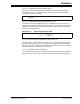
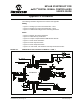
FIGURE A-2: DEBUG INPUT AND CONTROL SCHEMATIC – PART 2
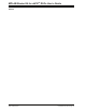
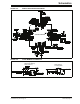
FIGURE A-3: USB INTERFACE/TARGET POWER SWITCHING SCHEMATIC
Serial EEPROM
Status LED - Debug
PIC18F67J50 Bypass/Decoupling Capacitors
USB Interface
(Bus Powered)
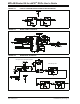
3.3V LDO
Linear Regulator
Host MCU Switchable
3.3V Regulated Supply
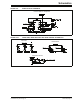
Status LED -
System Power