
User`s guide


Hardware
© 2008 Microchip Technology Inc. DS51700A-page 29
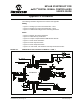
4.3.2.12 MICROPHONE GAIN CONTROL (R56)
MIC ADJ Potentiometer R56 (Ref A12) controls the gain of the Line/Microphone
Pre-Amplifier (U10:A). The default setting is with the arrow on the potentiometer
pointing to the arrow on the board.
4.3.2.13 LINE/MICROPHONE PRE-AMPLIFIER (U10:A)
The Microphone/Line Pre-amplifier (Ref A13) is implemented using one of the four
op-amps on the MCP6024 quad op-amp IC (U10). The output of this non-inverting AC
amplifier is biased at 1.65V. The gain of the amplifier is controlled by Potentiometer
R56, as given by Equation 4-1.
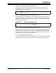
EQUATION 4-1: INPUT PRE-AMPLIFIER GAIN
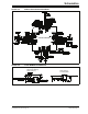
4.3.2.14 ANTI-ALIASING LOW-PASS FILTER (U10:B,C,D)
The Anti-Aliasing Low-Pass filter uses three of the four operational amplifiers on the
MCP6024 quad op-amp IC (U10). The output of the Line/Microphone Pre-Amplifier
(Ref A14) uses an anti-aliasing low-pass sixth order Sallen-Key structure to filter the
signal and provide a cut-off frequency of 3300 Hz.
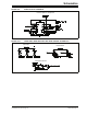
4.3.2.15 USER SWITCHES (S2 AND S1)
The starter kit features two press switches which are connected to the I/O ports on the
dsPIC33F device. The function of these switches is defined by the user application.
Note: Setting the gain too high can cause the output of the amplifier to saturate
and clip.
Gain 1
R56 R50+()
R44
-------------------------------
⎝⎠
⎛⎞
+=