
User`s guide


MPLAB STARTER KIT FOR
dsPIC
®
DIGITAL SIGNAL CONTROLLERS
USER’S GUIDE
© 2008 Microchip Technology Inc. DS51700A-page 23
Chapter 4. Hardware
This chapter provides a functional overview of the MPLAB Starter Kit for dsPIC
®
Digital
Signal Controllers and identifies the major hardware components. Topics covered
include:
• Audio Functional Overview
• Debug Functional Overview
• Board Components
4.1 AUDIO FUNCTIONAL OVERVIEW
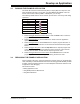
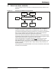
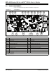
The block diagram shown in Figure 4-1 illustrates the mainstream operation of the
starter kit.
FIGURE 4-1: STARTER KIT BLOCK DIAGRAM
4.1.1 Speech Sampling
The incoming audio signal can come from a line input or a condenser microphone. The
speech sampling input is jumper selected (J7). The selected signal is amplified by a
non-inverting AC amplifier (Line/Microphone Amplifier) and routed to the ADC module
on the dsPIC33F device through an anti-aliasing filter. This sixth-order Sallen-Key
low-pass filter has a cut-off frequency of 3300 Hz. The output of the anti-aliasing filter
is connected to input AN0 of the ADC module on the device. If the input to the amplifier
is a condenser microphone, a bias voltage provides a working supply voltage for the
microphone. The line input does not require this bias voltage.
J6
dsPIC33F
AN0
AN4
OC1
MICROPHONE
LINE INPUT
LOW-
PASS
FILTER
HEADPHONES
HEADPHONE
AMPLIFIER
LINE/MIC
SELECT
LINE/MICROPHONE
AMPLIFIER
SPI
4 Mbit
FLASH
MEMORY
CODEC
DCI
OUTPUT
SELECT
J7
3 db to 23 db
-33 db to 12 db
ANTI-
ALIASING
FILTER
LOW-PASS
TEMPERATURE
SENSOR
Out
In
AUDIO
I
2
C™
Device